H0006 Procedure for Changing the Hydraulic Pump on SB300, SB330 and SB360 Sidelifters

7 May 1999 PDF File

Hydraulics

Version 1


SBnote

We recommend that you analyse the oil quality every time you change a hydraulic pump. If this is not a viable option then yuo should change the oil and the filters at the same time.

Disconnect the battery.

  1. Close the oil tank isolating valves.
  2. Disconnect the low and high pressure hoses from the pump (cap hoses).
  3. Remove the bolts securing the pump mounting plate to the bell housing and withdraw the pump. Remove the male drive couplings and plate assembly.
  4. Inspect both the engine and pump drive couplings and the plastic sleeve for signs of wear, replace parts as required.
  5. Fit up pump to its mounting plate, fit the drive coupling to the pump shaft using new key tab washer and nut, torque the nut and lock the tab washer.

    Nut torque for MK4 and MK5 = 40Nm (30 ftIbs). Nut torque for SB300, SB330 and SB360 = (170NM 125ftlbs)

  6. Fit the plastic sleeve and mount pump assembly to the bell housing.
  7. Carry out oil change or establish oil quality (change oil if necessary) and fit new oil filters. Refer oil change procedure Sidelifter Service Info H0007
  8. Connect low and high pressure hoses and TURN ON OIL TANK ISOLATING VALVES Top up oil level as required.
  9. Commission pump as in the following instructions.

Commissioning the Pump on SB300, SB330 and SB360 Sidelifters

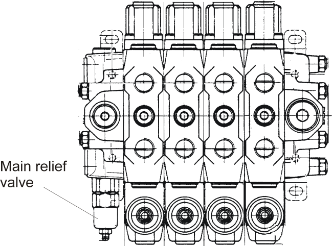
  1. Back off the main relief valve adjustment on the Left Hand Danfoss Control Valve by two full turns of the adjustment screw. Screw the Right Hand Danfoss relief adjustment all the way in. Refer 2 below. See also Service Info H0005.

  2. Reconnect the battery and start the engine. Allow the engine to run for few minutes to circulate oil through the system.
  3. To set the relief valve it is advisable to connect an accurate oil pressure gauge 0-300 Bar in place of the existing Sidelifter gauge.
  4. Starting with rear crane, lower the top arm to the end of its stroke and read the pressure while holding the control lever. When you can get a steady reading, if necessary make small adjustments to the relief valve until you get a reading of 275 Bar (4000PSI).

    SBnote

    The pump will require bedding in and will drag the engine speed down during the initial high pressure checks.

  5. Lower the front top arm and read off the pressure while holding the control lever. If this pressure is lower than achieved on the rear valve, screw in the Left hand relief adjustment to achieve a pressure of 285 Bar (4200 PSI) max on the left hand crane. This should give a pressure of 275 Bar (4000 PSI) on the right hand crane. The reason for the pressure difference and response time between the front and the rear valves is the length of the load sensing lines (LS).
  6. Check hoses and fittings for leaks.
  7. Check pump and bell housing mounting bolts are secure.

Commissioning the Pump on Mk4 and Mk5 Sidelifters

  1. Back off the main relief valve adjustment on both Cassappa control valves by two full turns of the adjustment screw. Refer 2 below.
  2. Reconnect the battery and start the engine. Allow the engine to run for a few minutes to circulate oil through the system.

  3. To set the relief valves it is advisable to connect an accurate oil pressure gauge in place of the existing Sidelifter gauges.
  4. Starting with rear crane, lower the top arm to the end of its stroke and read the pressure while holding the control lever down. Once a steady reading is observed small adjustments can be made to the relief valve to obtain a reading of 4000 PSI (275 Bar). Secure the adjustment locking nut and recheck the pressure. Carry out the same procedure for the front crane.
  5. Check hoses and fittings for leaks; check pump and bell housing mounting bolts are secure.