H0005 Danfoss PVG Main Relief Valve Adjustment SB360, SB300, SB330 with Load Sensing
05 Aug 2003 PDF File
|
Hydraulics
|
Version 3
|
|
These machines are equipped with two Danfoss PVG 32 control valves, interconnected by a load sensing line. These control valves differ in that the pump side modules (where the pump oil enters the valve and the tank oil exits) are "Open Centre" or "Closed Centre".
"Open Centre" valves have the LS (load sensing) connection entering the pump side module and a LX connection exiting the end plate. They are marked with part No 157B5110
"Closed Centre" valves have the LS (load sensing) connection entering the pump side module only. They are marked with part No 157B5111
Valve part No 157B5110 is fitted to the left hand (L/H) crane (LS Amplifier on trombone)
Valve part No 157B5111 is fitted to the right hand (R/H) crane.
See orientation for left hand and right hand valves in the front section of the parts manual.
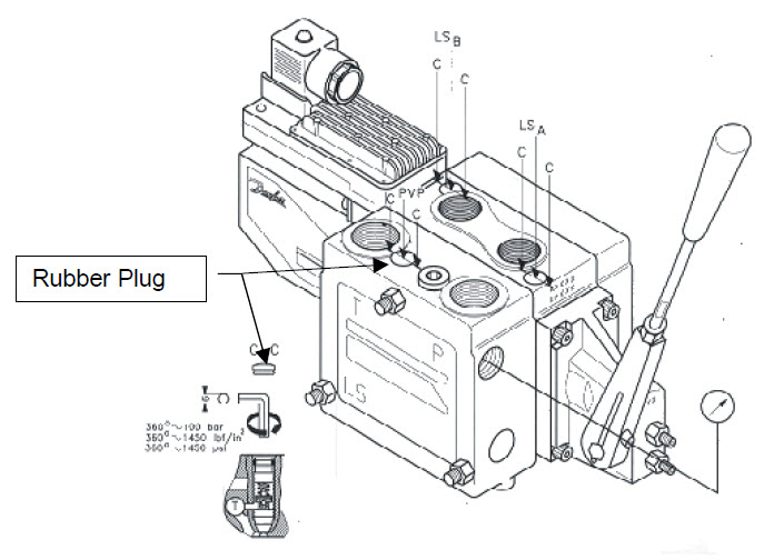
- Remove the rubber plug to access the adjustment screw located close to the tank return port on the pump side module (P#157B5111) R/H crane, screw the relief adjustment all the way in.
- Locate the relief adjustment screw on the pump side module (P#157B5110) for the L/H crane back this adjustment off by two full turns (6mm hex key) anticlockwise (To avoid over pressurising the system and pump).
- Start the engine and select low speed and arm functions, lower the front and rear top arms together and with the cylinders bottomed out read off the system pressure, carry out small adjustments to obtain a pressure of 275-285 Bar (4000-4150 PSI). Operate each arm independently and check the pressures.
- There can be up to 14 Bar (200 PSI) difference between left and right cranes.
- Apply grease to the cavity and replace the rubber plug.