![]()
![]()
![]()
![]()
|
|
|
|
|
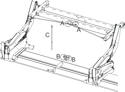
The sensor lights are mounted on the two back corners of the Top Lift Frame, where they are visible to the operator.
There is a pair of each colour stacked vertically. As discussed in, each colour indicates a different state while positioning and then attaching the Top Lift Frame to the container. To summarise, these are:
Green: |
Twistlocks Locked |
Amber: |
Top Lift Frame sitting on Container |
Red: |
Twistlocks Unlocked |
Flashing Red: |
Twistlocks between locked and unlocked positions, note that Arms Mode is disabled in this condition. Can also indicate a sensor failure. |
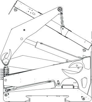
When the Sidelifter is not in use with the Top Lift Frame attached, particularly during transporting, it will be necessary to secure the frame to the Sidelifter. This is done using stowage poles that are stowed along the lifting side long beam of the Topl Lft Frame as shown in the diagram below.
To stow and secure the Top Lift Frame, follow these steps: