S0016 PDF File |
Version 2 |
Structural |
August 2012 |
Refer to document T0001 for details of applicable loads for physical testing of Steelbro chain.
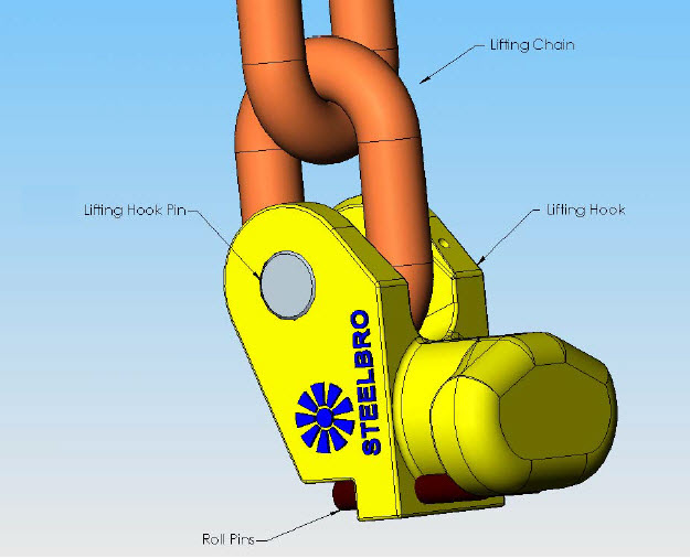
The lifting lugs consist of 4 main components as pictured in figure 1.0.
Figure 1.0: Lifting lug components.
Chain is manufactured from hardened and tempered steels to meet the critical requirements of this grade and has a high resistance to impact and wear. The useful life of Steelbro chain slings can be extended by the following practices:
It is important to inspect chain slings regularly. The inspections should include the following:
|
Minimum Permissible Diameters |
|
Chain Size (mm) |
Crown (mm) |
Elsewhere (mm) |
10 |
8.0 |
8.5 |
13 |
10.2 |
10.8 |
16 |
12.8 |
13.6 |
20 |
16.0 |
17.0 |
|
Minimum Permissible Diameters |
|
Chain Size (mm) |
Crown (mm) |
Elsewhere (mm) |
10 |
9.0 |
9.0 |
13 |
11.7 |
11.7 |
16 |
14.4 |
14.4 |
20 |
18.0 |
18.0 |
|
Minimum Permissible Diameters |
|
Chain Size (mm) |
Crown (mm) |
Elsewhere (mm) |
16 |
14.4 |
14.4 |
20 |
18.0 |
18.0 |
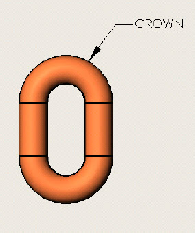
Figure 2.0: Chain illustration showing crown
The lifting hook pins are an alloy steel, which is heat treated to produce a high strength material. These pins are strong but not malleable and will not tolerate large amounts of deflection. The pins should not freely rotate due to the roll pin locking mechanism used however the chain should be free to move around the pin.
Safe use of these pins, requires regular inspections of the pins. Inspections that are required are as follows:
Pin Wear Allowance:
Pin diameter (mm) |
Minimum permissible diameter (mm) |
22 |
21 |
If pin wear exceeds the specified allowance then pin must be replaced.
The lifting hook is cast from high-grade steel. The lifting hook has 4 main areas, which are; the clevis ears, the shaft, the shaft ears and the body. They are shown in figure 3.0 below. The lifting hook requires regular inspections.
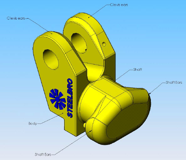
Figure 3.0: Lifting hook
The clevis ears require the following inspections to be carried out daily:
|
Chain Size |
Maximum Permissible size |
Minimum Permissible Size |
Gap between Clevis ears (mm) |
16 |
19 |
16 |
Gap between Clevis ears (mm) |
20 |
23 |
20 |
Pin Hole flogging mm) |
|
Ř 23.5 |
|
Lifting hooks exceeding the above stated allowances must be discarded and replaced.
The shaft requires visual inspection of its surface for cracking (specifically where it joins the body and shaft ears), gouging and deformation. If surface defects (previously stated) exceed 50% of surface then the part must be discarded and replaced.
These require inspection for cracking (particularly where they join the shaft) and gouging of the ears. No deformation of the shaft ears is tolerated but a wear allowance of 2mm is allowed. If the shaft ears do not conform to the wear allowance or have deformed then the lifting hook must be replaced.
Roll pins must be inspected for deformation of any type (out of roundness, gouging, bending along shaft, etc). If deformation exists in the roll pins then they should be replaced immediately.
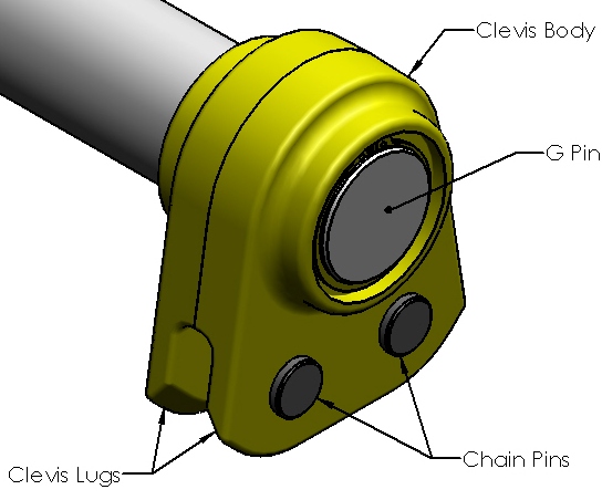
This pin is not specified as lifting gear but must be inspected along with the lifting gear. There are two types of G pin:
The following inspections are required on both types:
If the G pin has bound up and does rotate freely and/or surface wear is seen on the G pin then the specified Steelbro service agent should be contacted. If circlip is damaged then immediate replacement is required.
Clevis type G pins require these further inspections:
Chain Pins - The chain pins are an alloy steel, which is heat treated to produce a high strength material. These pins are strong but not malleable and will not tolerate large amounts of deflection. The pins should not freely rotate due to the roll pin locking mechanism used however the chain should be free to move around the pin.
Safe use of these pins, requires regular inspections of the pins. Inspections that are required are as follows:
Pin Wear Allowance:
Pin diameter (mm) |
Minimum permissible diameter (mm) |
22 |
21 |
If pin wear exceeds the specified allowance then pin must be replaced.
Clevis Lugs - The clevis lugs require the following inspections to be carried out weekly:
Wear allowances for Clevis Lugs:
|
Chain Size |
Maximum Permissible size |
Minimum Permissible Size |
Gap between Clevis lugs(mm) |
16 |
19 |
16 |
Gap between Clevis lugs(mm) |
20 |
23 |
20 |
Pin Hole flogging mm) |
|
Ř 23.5 |
|
Units exceeding the stated allowances must be discarded and replaced.