S0037 Top Arm Installation
S0037 PDF File
|
Version 1
|
Structural
|
27 August 2008
|
For the location of pins, refer to Service Info S0028 Crane Pin Names.
Equipment Required:
- Cradle (purpose made tool)
- Lifting strop or jig
- Overhead crane
- Pin puller
- General tools
How to install a top arm
Before starting this procedure, ensure the Sidelifter is on level ground. Note that the model shown below is a SB361.
- Untie the rope securing the bottom arm and top lift cylinder.
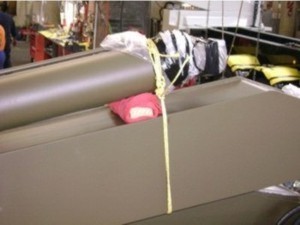
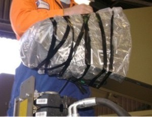
- Remove the packaging protecting the end of the top arm and securing the sensor cabling.
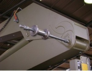
- Remove the retaining bolts from the F-pin. Use a pin puller to carefully remove the F-pin from the top lift cylinder.
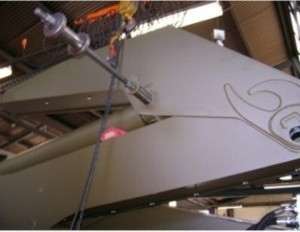
- Lift the top arm into position. The procedure for lifting the top arm depends on the crane model.
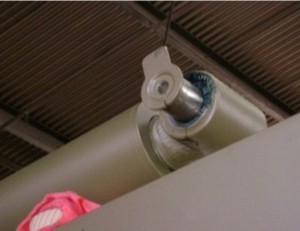
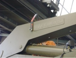
For models with 16mm centre plugs, remove the 16mm plugs from the centres of both sides of top arm and fit a 16mm bolt 130mm long into the plug threads. Fit a lifting strop or chain over these bolts. With an overhead crane, or similar lifting equipment, take the weight of the arm. Attach a strop or chain from the overhead crane to the G-pin, this will help with balance.
For models without central plugs, e.g. older SB360's, use the SB360 lifting jig - attach the four chains to the four corner pins of the arm.
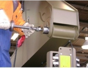
Apply Coppercoat Anti-seize to the F-pin and then use a pin puller to carefully insert the pin through the top arm and the top lift cylinder. Apply Loctite to the the F-pin retaining bolts and tighten.
Apply grease through the grease nipples on the F-pin until grease runs freely from the housing.
- Apply Coppercoat Anti-seize to the D-pin and then use a pin puller to carefully insert the pin through the bottom and top arms. Apply Loctite to the the D-pin retaining bolts and tighten. Apply grease through the grease nipples on the D-pin until grease runs freely from the housing.
Ensure you remove the wooden shipping block as this can fall down inside the bottom of the cylinder and cause damage when the arms are fully folded.
- Remove the lifting jig and the strop or chain from the top arm.
- Connect the sensor cables. When connecting the angle sensor cables ensure that the metal parts are tight. Use pliers or similar, as finger tight is not sufficient to make the connection water tight against the internal O-ring.
- Test sensor values after the cables are connected. Refer to Step 11 of the Service Info SL0005 Calibrating SMARTlift Angle Sensors Using the Plumb-Bob Method for this procedure.
- Check that the worklamps are functioning correctly. You may need to fit top arm worklamps if they are supplied. These are usually stored in the tool box in the middle of the Sidelifter.
- Complete the procedure P0010 Post Top Arm Installation Inspection and return to Product Support.