SL0005 Calibrating SMARTlift Angle Sensors Using the Plumb Bob Method

SL0005 PDF File

Version 3

SMARTlift

17-05-2011

Calibration procedure for SMARTlift SB330/200/361/401

Safety precautions for SMARTlift Calibration

Special Tool Requirements for SMARTlift Calibration

Trailer Leveling

Instructions

  • Place the spirit level firstly along the chassis rails and secondly across the chassis rails.
  • Use hydraulic jacks to level the trailer, in camber (across) and elevation (along).

1. Calibration


  • Start the engine on the Sidelifter and wait for the Smartlift System to Boot Up on the Smartlift LED Screen.


  • Use the rotary switch to enter the MAIN MENU menu and select the MANUFACTURERS AREA.


2. Calibration


  • Enter the Manufacturers Area Code: and press the rotary switch in to enter the code.
  • IMPORTANT: When Calibrating the angle sensors make sure that the engine is not running, so as to avoid unnecessary vibrations.

3. Calibration


  • Enter the MANUFACTURERS AREA. , highlight the Angle Sensor Calibration option and select it by pressing the rotary switch.

4. Calibration


  • Highlight the Calibrate Individual Angle Sensors option and select it by pressing the rotary switch.

5. Calibration


  • The Calibration of the individual angle sensors must be completed in the approved sequence order working from the crane base upwards.

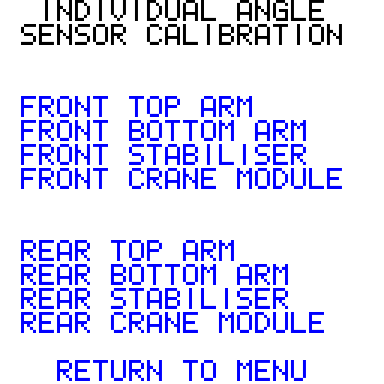
The approved sequence for calibration is:

  1. Front Crane Module
  2. Rear Crane Module
  3. Front Stabiliser
  4. Rear Stabiliser
  5. Front bottom Arm
  6. Rear bottom Arm
  7. Front Top Arm
  8. Rear Top Arm

6. Calibration


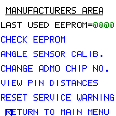
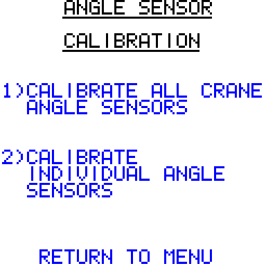
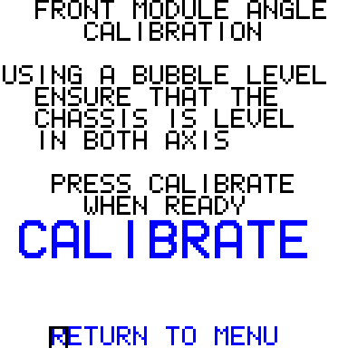
When the chassis is confirmed to be level on both axes and the cranes are in their full folded positions

ENSURE THAT THE DIESEL ENGINE IS NOT RUNNING.

Select the Front Module Angle Calibration option and move to the CALIBRATE option. Press the rotary switch in to select the Calibrate option.

The calibration should now be complete and the CALIBRATION OK message. (If the CALIBRATION FAILED message flashes then ; inform STEELBRO Product Support) Once completed repeat process again with the rear module. It is now ok to start the engine.

7. Calibration


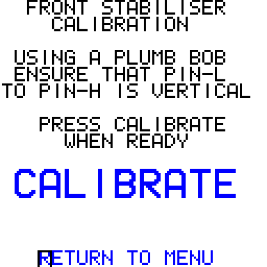
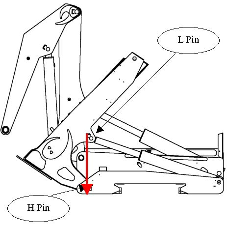
When both crane modules have been calibrated select the Front Stabiliser option.

  • Hang a plumb bob from the L Pin as in the diagram below.
  • Move the stabiliser until the plumb bob is vertical from the L Pin to the H Pin.
  • You have a Tolerance at the H Pin of ±10mm.
  • For all Calibration Tasks that require the use of plumb bobs the powerpack must be turned off once the plumb bob is in the required position.

8. Calibration


  • Enter the Angle Sensor Calibration option and select the Calibrate Individual Angle Sensors. Press the Rotary Switch in to select the option.


  • Select the Front Stabiliser folder move to the CALIBRATE option and press the rotary switch in. The calibration should now be complete and the CALIBRATION OK message will flash. (If the CALIBRATION FAILED message flashes; inform STEELBRO Product Support) Once completed repeat process again with the Rear Stabiliser.

9. Calibration


Once you have calibrated the Stabilisers you must now move to the Bottom Arms starting with the front unit.

  • Begin by hanging a Plumb Bob from the D Pin as in the diagram below.
  • Move the Bottom Arm until the Plum Bob is vertical from the D Pin to the A Pin.
  • You have a Tolerance at the A Pin of ±10mm.
  • For all Calibration Tasks that require the use of Plumb Bobs the Powerpack must be turned off once the Plumb Bob is in the required position.


10. Calibration


  • Enter the Angle Sensor Calibration folder and select the 2ND folder: Calibrate Individual Angle Sensors. Press the Rotary Switch in to enter the folder.


  • Select the Front Bottom Arm folder move to the CALIBRATE portion of the screen and press the Rotary Switch in. The calibration should now be complete and the CALIBRATION OK folder will flash. (If the CALIBRATION FAILED folder flashes; inform Steelbro electrical staff) Once completed repeat process again with the Rear Bottom Arm.

11. Calibration


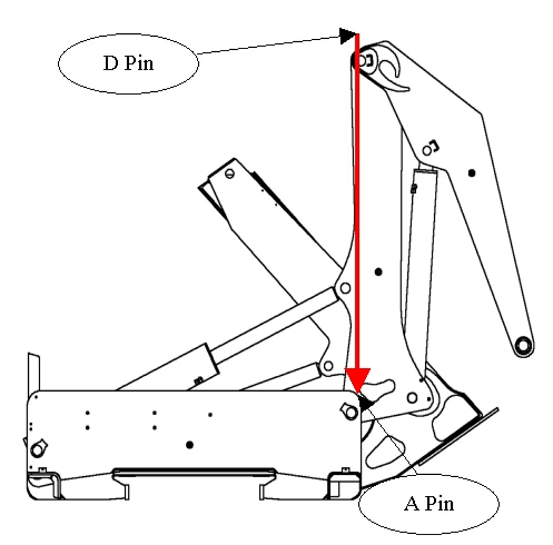
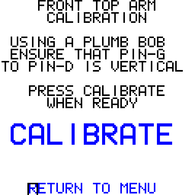
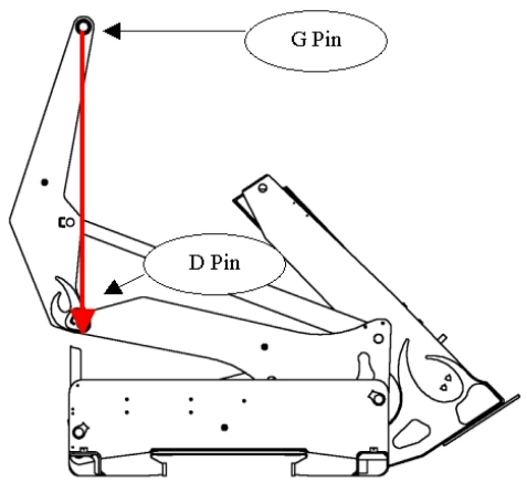
Once you have calibrated the Bottom Arms you must now move to the Top Arms starting with the front unit.

  • Begin by hanging a Plumb Bob from the G Pin as in the diagram below.
  • Move the Bottom Arm until the Plum Bob is vertical from the G Pin to the D Pin.
  • You have a Tolerance at the D Pin of ±10mm.
  • For all Calibration Tasks that require the use of Plumb Bobs the Powerpack must be turned off once the Plumb Bob is in the required position.


12. Calibration


  • Enter the Angle Sensor Calibration folder and select the 2ND folder: Calibrate Individual Angle Sensors. Press the Rotary Switch in to enter the folder.
  • Select the Front Top Arm folder move to the CALIBRATE portion of the screen and press the Rotary Switch in. The calibration should now be complete and the CALIBRATION OK folder will flash. (If the CALIBRATION FAILED folder flashes; inform Steelbro electrical staff) Once completed repeat process again with the Rear Top Arm. The Sidelifter is now fully Calibrated.


Important – Verification

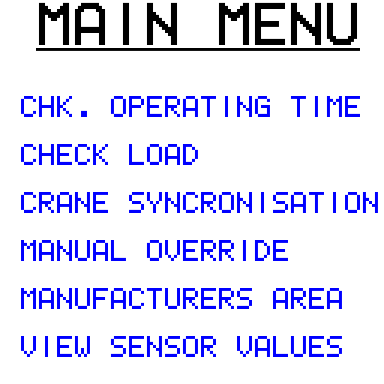
With the Trailer Level: Fully fold away the Arms and Stabilisers on both cranes. From the MAIN MENU select VIEW SENSOR VALUES and select FRONT ANGLE SENSORS check that the angles equal (within ± 1 degree) those listed in the tables below, repeat for REAR ANGLE SENSORS.

for SB361


Stabiliser Angle*

11º

Top Arm Angle

16º

Bottom Arm Angle

167º

Front Elevation

Front Camber

For SB401


Stabiliser Angle*

11º

Top Arm Angle

18º

Bottom Arm Angle

167º

Front Elevation

Front Camber

For SB330


Stabiliser Angle

Top Arm Angle

10º

Bottom Arm Angle

159º

Front Elevation

Front Camber

* Note: For machines equipped with tromboning stabiliser extensions: The angle when fully folded will equal 0º