![]()
![]()
![]()
![]()
|
|
|
|
|
The figure below shows the location of the electrical junction boxes on the Sidelifter. The state of the LEDs in the E box, and the F and R boxes can be used for initial fault finding.
Junction box E is located about midway down the side of the Sidelifter chassis.
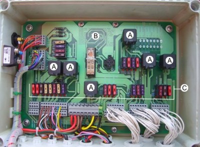
This is the main junction box and controls engine functions. It contains most of the fuses and relays.
Key: |
|
A |
Relay switches. A lit green LED signifies that the relay is energised. |
B |
Table showing fuse layout. |
C |
Fuses. A lit red LED indicates that the fuse is blown. |
Junction Box B is located at the rear of the Sidelifter.
Junction Box B runs the display screen and radio receiver.
Steer axle lock and lift axle override (where used) are also wired from this junction box.
There are no LEDs or fuses located in Junction box B
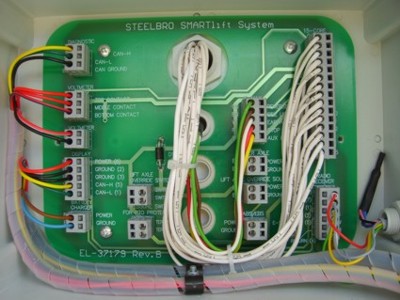
These junction boxes are located on crane modules. They connect sensor inputs and hydraulic valve controls on the crane modules. The circuitry layout of the F and R boxes is identical.
.jpg)
NOTES |
|
|
|