Page
Details
Sensor Values
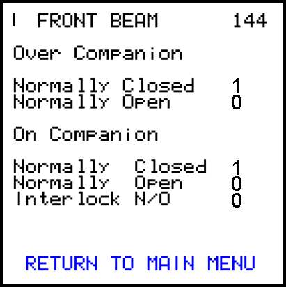
Accessed via
– View Sensor values
– View special options
Front Bridge Leg
or
Rear Bridge Leg
Stabiliser Mode
1 = On Companion Mode.
2 = Over companion mode.
December 2012 PDF File |
Technical Bulletin |
Version 1 |
Author: Mike Parker |
The bridge leg stabiliser option is available and is controlled by SMARTlift controls. This document shows the new SMARTlift display pages that relate to the bridge leg operations.
SB362
Page |
Details |
Sensor Values
|
Accessed via
– View Sensor values
– View special options
Front Bridge Leg or Rear Bridge Leg |
Stabiliser Mode
|
1 = On Companion Mode. 2 = Over companion mode. |
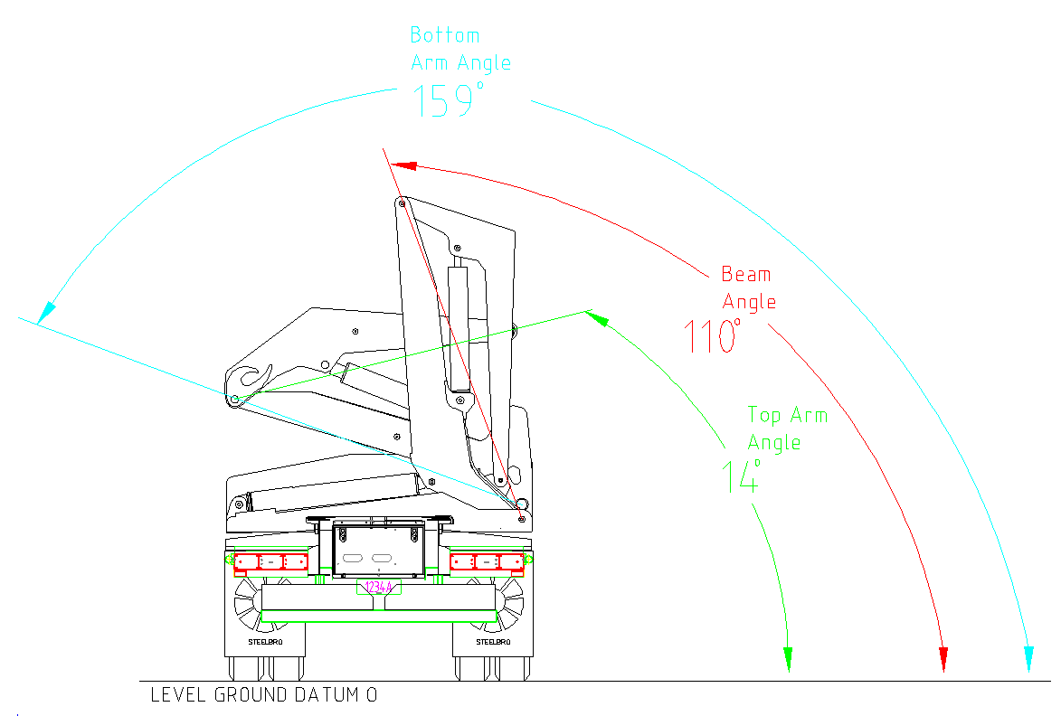
The diagram below shows the fully folded angle of the Bridge Leg stabiliser for calibrating the sensors with the L to H pin axis being vertical.
For SB362 - Bridge Leg Stabiliser |
Angle (Degrees) |
Stabiliser Angle – Bridge Beam |
110 |
Top Arm Angle |
14 |
Bottom Arm Angle |
159 |
Front Elevation |
0 |
Front Camber |
0 |
SW-42114 is for a SB362 Bridge Leg system.
SW-42106 v02 or higher is required for the display software.
Both files are available in software release 3 or higher available at www.steelbro-distributors.com
Operators manual for further alarms and operating details.
Wiring diagram EL-39199 Rev K for connection details. See www.steelbro-distributors.com for this and other versions of wiring diagrams.