Visual Check
Task
Firstly perform a visual check:
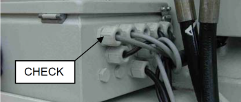
- Ensure that all junction box cable glands are tight,
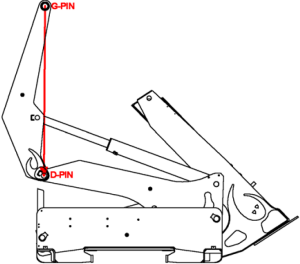
- Check all 8 angle sensors are securely fixed
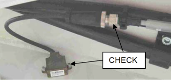
- Check all angle sensor plug/socket assemblies are tight.
- Check Pressure Sensor Plug is tight
10 Jan 2009 PDF File |
SMARTLift |
Version 1 |
Author: |
The following procedure should be followed in addition to the normal pre-delivery Sidelifter check.
Visual Check |
Task |
|
Firstly perform a visual check:
|
|
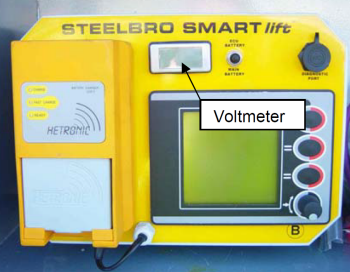
VoltageCheck |
Task |
|
|
Using the Voltmeter Toggle Switch, check the voltage of the Main Battery and ECU Battery. If the ECU Battery reads less than 11.5v run the alternator to charge the battery. |
|
|
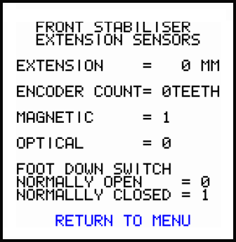
Stabiliser Extension Sensors |
Task |
|
|
Put the Sidelifter into Stabiliser Mode
|
|
|
||
Figure 2 |
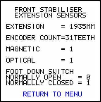
Stabiliser Extension Sensors |
Task |
|
|
With the Stabiliser fully extended check the values are as per Figure 3.
Put the Stabiliser Foot on the ground and observe the change.
Repeat this for the Rear Crane. |
|
|
||
|
||
|
||
|
||
Figure 3 |
SB401 Angle Sensors Check |
Task |
Figure 4 |
For an SB401:
|
SB330 Angle Sensors Check |
Task |
Figure 5 |
For an SB330:
|
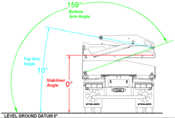
Angle Sensors Check |
Task |
Figure 6 |
|
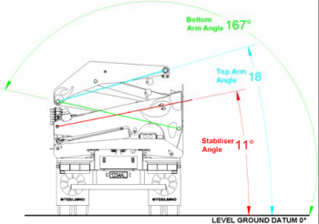
Stabiliser Angle Sensor Calibration Check |
Task |
Figure 7 |
|
Bottom Arm Angle Sensor Calibration Check |
Task |
Figure 8 |
xxxx = contact STEELBRO |
Top Arm Angle Sensor Calibration Check |
Task |
Figure 9 |
xxxx = contact STEELBRO |