19 Jul 2011 PDF File |
Structural |
Version 1 |
Author: |
SB450 Cranes
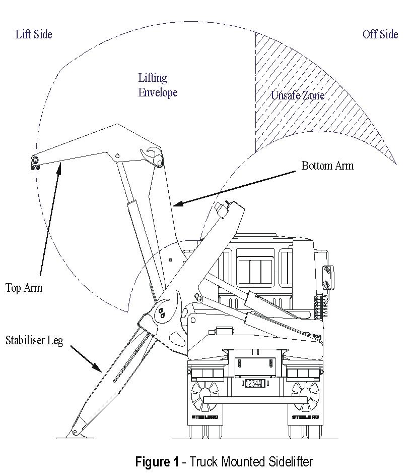
When operating a Steelbro crane set, the stability of the crane is primarily governed by three factors:
These can each be affected by other factors, i.e. the deck height limits how far out the stabiliser foot can reach when placed on the ground; the suspension lash effects the contribution of un-sprung mass to the effective tare.
When the cranes are not fitted with offside stabiliser legs, positioning the load past the centre of the deck in the offside direction can lead to instability.
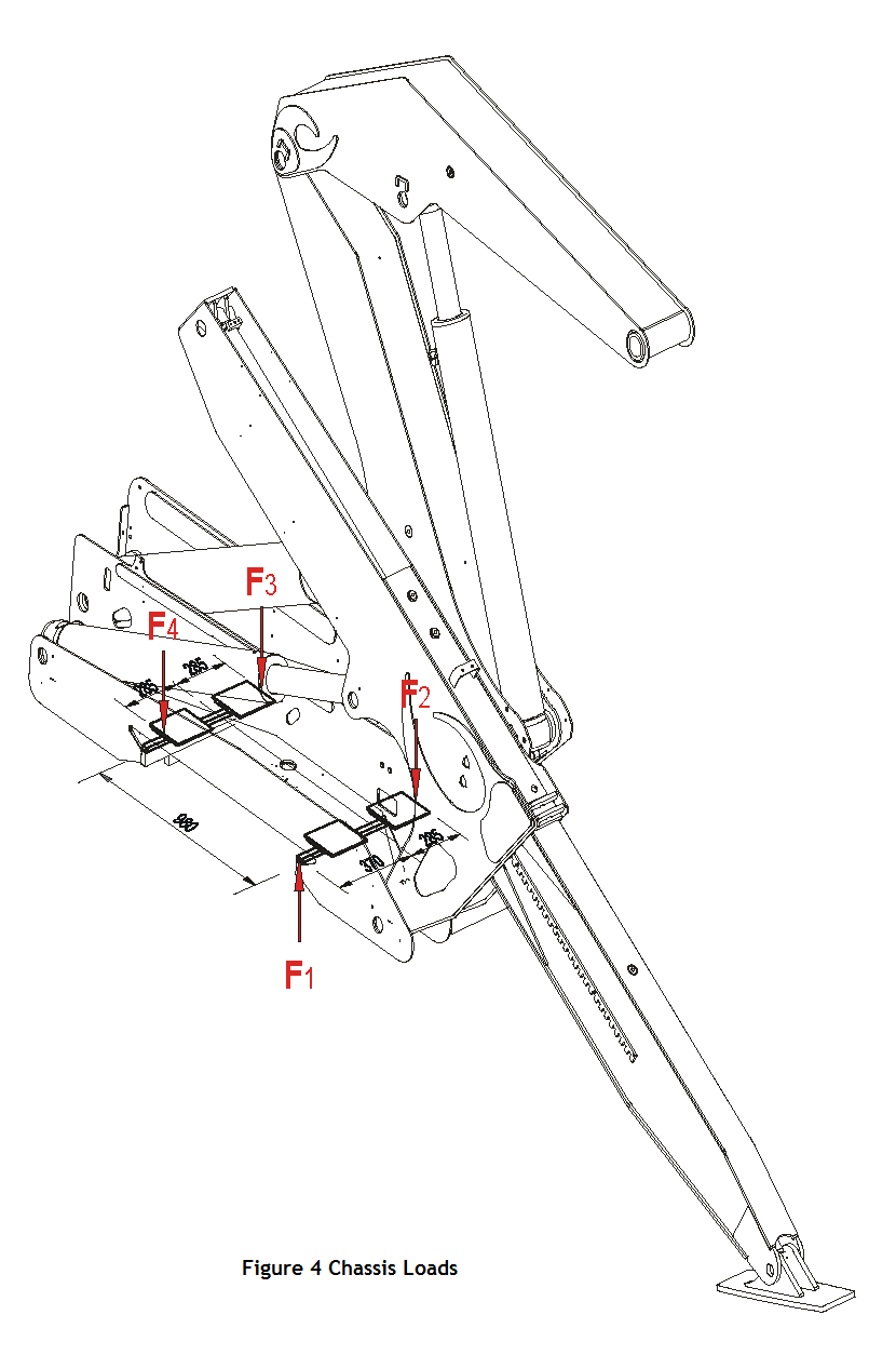
There are two extreme load conditions subject to the crane supports.
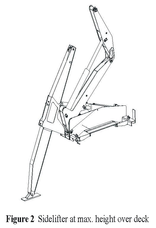
When the load is lifted to maximum height directly above the deck.
This produces the greatest amount of out-of-plane moment on the arms, causing the cranes to roll towards each other. The weight of the payload and the cranes is also fully bearing on the supports at this point. The load on the stabiliser leg is negligible. The mounting chassis/frame is required to be stiff enough to prevent these deflecting too far, causing the lifting pins or chains to contact the upper edges of the container. |
|
|
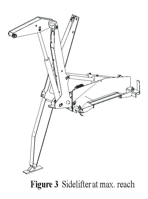
When the arms are at maximum reach. This makes the sum of all the support loads become vertically upward as the truck weight helps counterbalance the payload. The out-of-plane moment at the supports is greater as the stabiliser leg pushes the base upward and the load on the arms pushes down, causing the cranes to roll towards each other even more than condition 1. |
|
|
|
Model |
SB450
|
|
|
Condition |
1 |
2 |
Force |
F1 |
247.5kN |
274.5kN |
F2 |
271.1kN |
301.5kN |
|
F3 |
-12.4kN |
-13.5kN |
|
F4 |
-12.4kN |
-13.5kN |
|
Table 1 - Load Transferred into Chassis |
|||
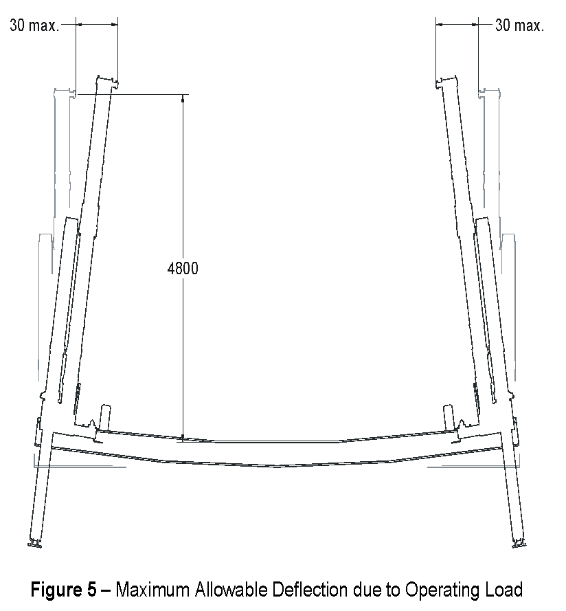
The design of the support frame or chassis is required to be stiff enough to prevent excessive deflection at the lifting pin (G Pin) on the crane. As long as the deflection at each crane due to the loads specified above, does not exceed 30mm at a height of 4800 above the support flange, then the correct operation of these units will be ensured.
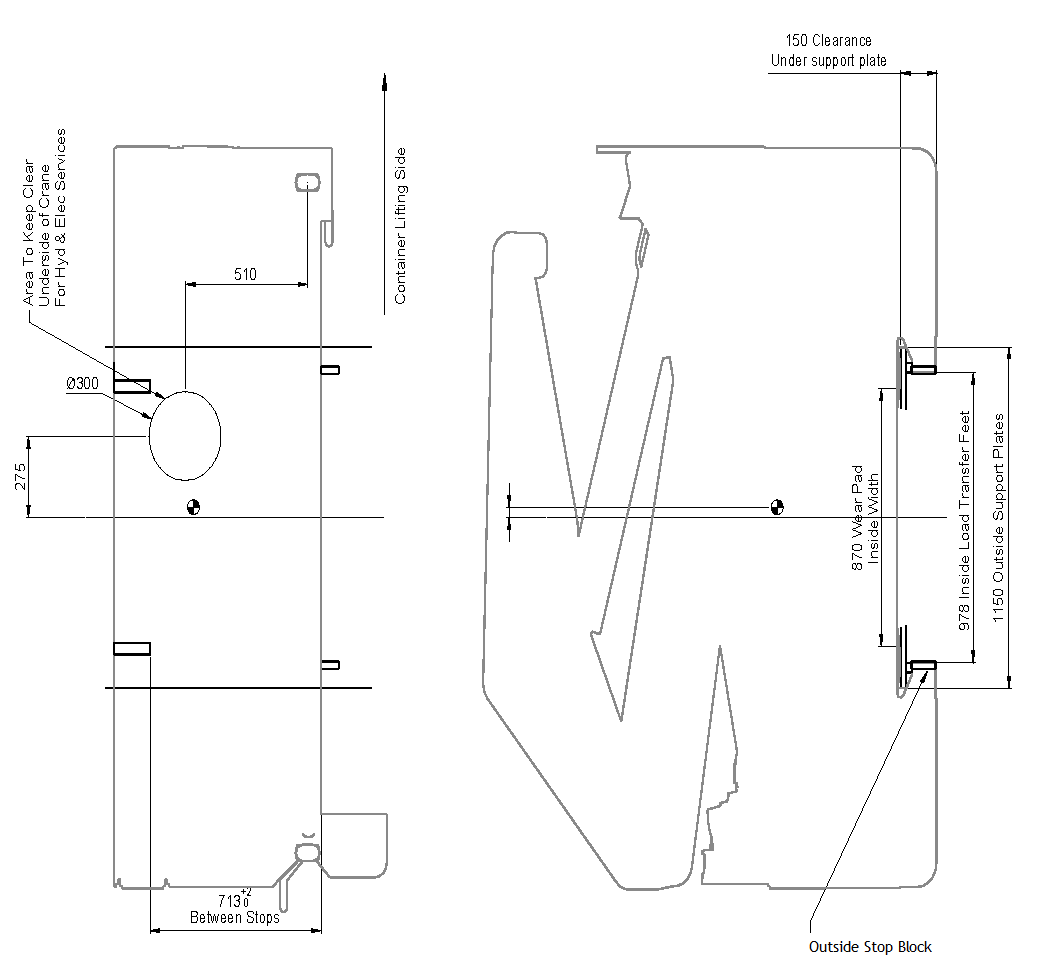
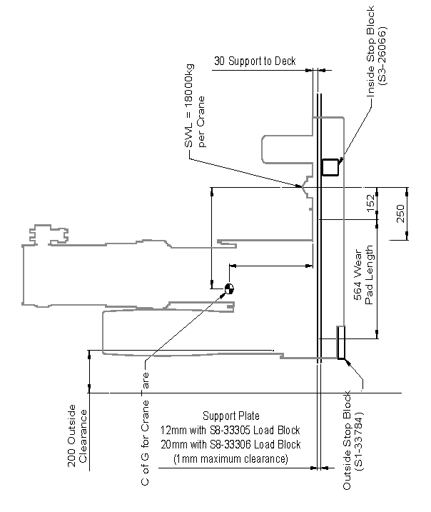
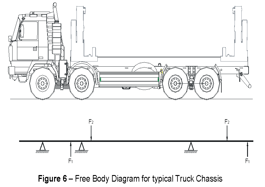
The load distribution for a typical truck mount is as shown below:
The majority of truck manufacturers recommend that the sub-frame be attached to the chassis in such a way that the original bending and torsional characteristics of the vehicle are retained. This does create some conflict with the requirement for the two cranes to maintain alignment and minimise rolling of the chassis during the lifting process.
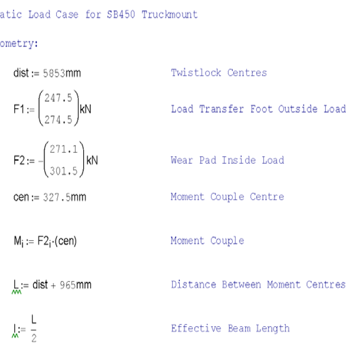
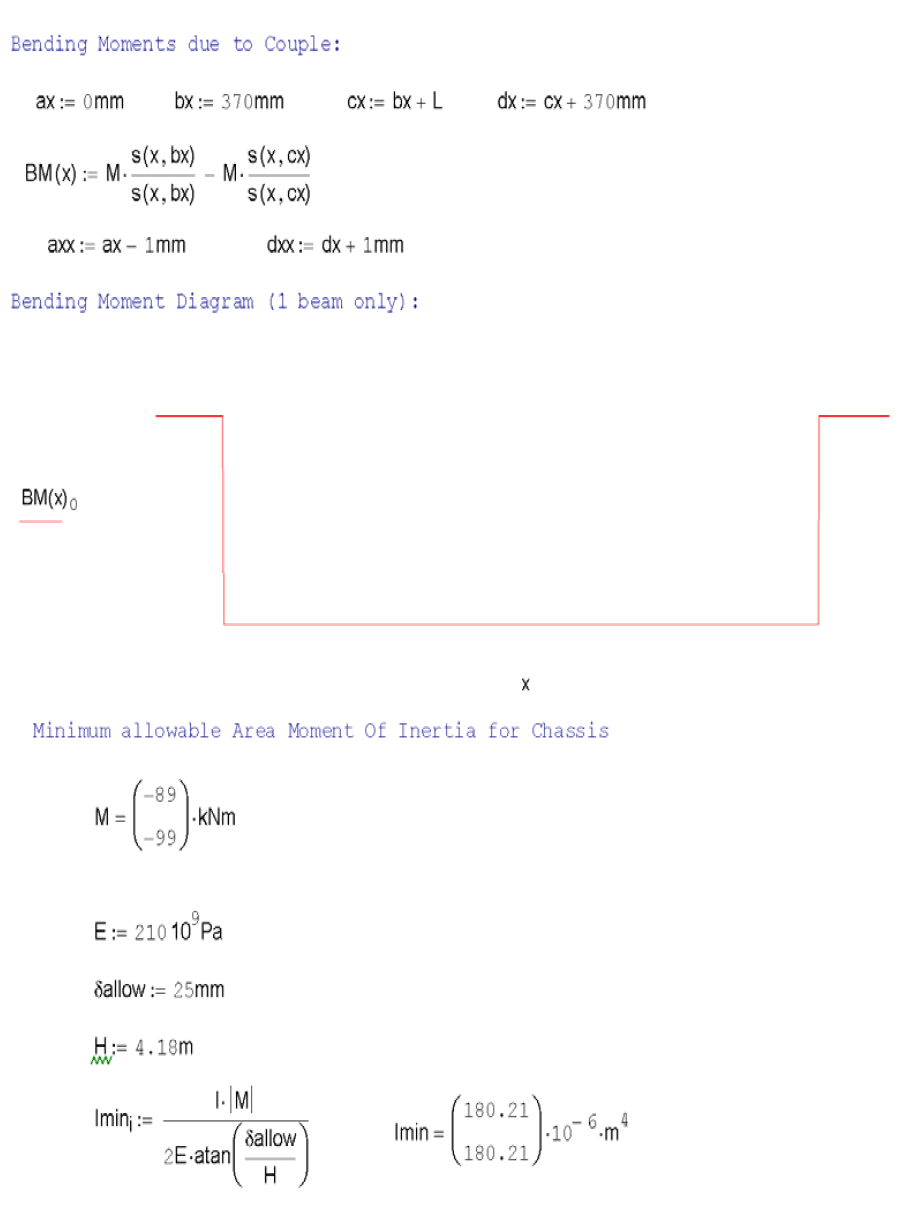
As the exact arrangement of supports will vary from installation to installation the following calculation has been carried out with assumptions i.e. consider the loads to be taken solely by one beam. The most critical aspect identified for proper crane operation is the amount of deflection allowed by the support frame/chassis. The following diagram considers only the opposing moment couples generated by the rolling of the cranes towards each other. From these we can determine the minimum chassis strength required to resist deflection if not taking axle supports into account.
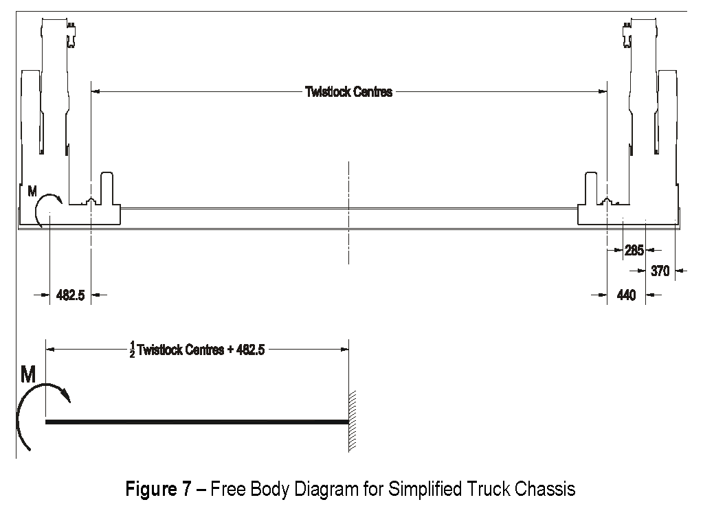
Considering only one beam on the lift side of the truck to be resisting the moment couple, this will give a conservative stiffness requirement.
Recommended double stacking twistlock height 1350mm.
Model |
SB450 |
I (m4) |
180.21 x 10⁻⁶ |
Table 2 - Minimum Area Moment of Inertia Values for 20 Foot Supporting Chassis |
|
Approximate SB450 crane tare 2800kg. (per cranes – no fittings/subframe included)
To ensure correct operation of the cranes, it is important that the support frame is installed onto the vehicle such that it is parallel to the ground. Recommended double-stacking twistlock height is 1350mm. |
|