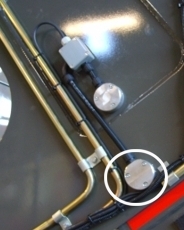
Position of sensors on SB330 - lower sensor circled
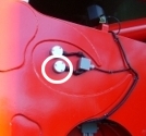
Position of sensors on SB361 and SB401 - lower sensor circled. (On Bending Legs it is the top sensor)
SL0016 print pdf |
Version 1 |
SMARTlift |
22 May 2007 |
This is the procedure for replacing the current optical sensors and encoder strips on SMARTlift units with a magnetic sensor and encoder strip.
Note: The process differs slightly between Standard Leg and Bending Leg style stablisers, this will be mentioned where relevant.
Below are the parts kits needed to carry out a retro fit on an existing unit.
Part No |
Description |
QTY |
EL-37324 |
Kit Magnet Mod Stabiliser Extend Sense |
|
EL-37327 |
#Encoder Strip Assy Magnet |
2 |
EL-32920 |
Sensor Magnetic Proximity |
2 |
EL-37328 |
Cutter - 24mm |
1 |
EL-32921 |
Magnet MAG-2006-B (M3.0) |
2 |
FA-28827 |
Washer Flat M8X19 ZP |
6 |
FA-33663 |
Screw Socket Countersink M4x16 ZP |
2 |
Part No |
Description |
QTY |
EL-37350 |
Kit Magnet Mod Stab Sense BLeg |
|
EL-37352 |
#Encoder Strip Assy Magnet BLeg |
2 |
EL-32920 |
Sensor Magnetic Proximity |
2 |
EL-37328 |
Cutter - 24mm |
1 |
EL-32921 |
Magnet MAG-2006-B (M3.0) |
2 |
FA-28827 |
Washer Flat M8X19 ZP |
6 |
FA-33663 |
Screw Socket Countersink M4x16 ZP |
2 |
|
|
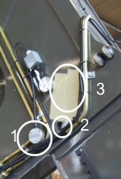
Position of sensors on SB330 - lower sensor circled |
Position of sensors on SB361 and SB401 - lower sensor circled. (On Bending Legs it is the top sensor) |
The sensor that needs changing is on the stabiliser housing. There are two sensors, only the lower one is changed in this procedure. The positions of the sensors are different for SB330's and SB361/SB401's, as illustrated above. On the SB361 Bending Leg stabiliser, the two sensors are swapped over so it is the higher one that is swapped out.
Photos show SB330 but the details are the same for the SB361/SB401.
There are three stages to this process, the related procedures for each are below.
A magnet needs to be added to the internal part of the stabiliser extension. To do this, follow the steps below:
Step |
Action |
Notes |
|---|---|---|
1 |
Before starting, ensure stabiliser extension is out FULLY. This is essential for correctly positioning the magnet. |
|
2 |
Unscrew the sensor housing (1) and move aside. Beneath it is a hole in the housing (2). |
|
3 |
Tape the area near the hole to protect paint work from drill (3) |
|
4 |
Mark the centre of the area of stabiliser extension visible through the hole (2) clearly and drill a pilot hole on the mark (4).
|
|
5 |
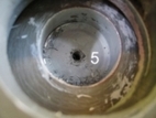
With 24mm cutter provided, use magnet drill to cut down just through the outer double layer of stabiliser extension only. Note: Do not drill right through! Remove plug |
Ensure the drill has a spring loaded guide so that the bottom of the hole remains flat for step 6. |
6 |
In the exact centre of the new hole, drill and tap a hole with 3.2mm drill and M4 Tap (5). |
|
7 |
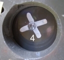
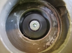
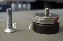
Onto countersink screw provided (6) stack the magnet and three washers and screw into hole using Loctite. DON'T OVERTIGHTEN SCREW as the magnet will crack easily. Screw in gently - the loctite will prevent the screw falling out.
This photo (above) shows the correctly inserted screw. Surface of magnet will be slightly below flush with the extension surface. |
|
This procedure involves removing the optical sensor from its housing and junction box, and replacing with a magnetic sensor.
Step |
Action |
Notes |
|---|---|---|
1 |
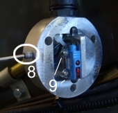
Sensor housing is already disconnected from the Stabiliser Housing. Remove the grub screws from each side using an allen key (8) and using the holes for access, unscrew the mounting screws (9). |
|
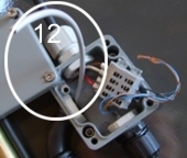
2 |
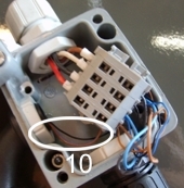
Remove the Junction box cover and disconnect the optical sensor wires (10) from the junction. Now pull the optical sensor right out, including the mount plate as it is not required for the magnetic sensor. (SB330 model only) |
|
3 |
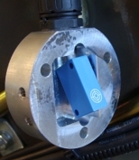
Thread the magnetic sensor cable up (or on the Bending Leg, down) through the conduit to the junction box, ensuring the white target on the side of the sensor is facing out as in the photo (right). |
|
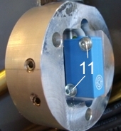
4 |
Fasten the sensor into the housing using a flat washer flush to the sensor and the lock washer then the screw. When both screws are fastened (11) replace the grub screws on the side of the sensor housing. |
|
5 |
At the junction box housing, cut the magnetic sensor cable to about 150mm and strip back. |
|
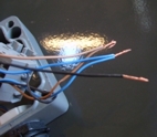
6 |
Twist colour pairs together (brown and blue). Black one is single. |
|
7 |
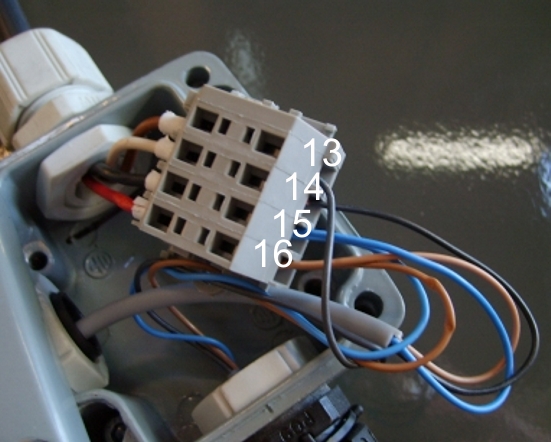
The black wire (13) should already be attached to the junction box (it connects the other magnetic sensor). Attach wires into junction box in this order, black (14), blue pair (15) and brown pair (16). Reattach sensor housing to stabiliser and junction box cover. (except for SB361 or SB401 - |
|
Step |
Action |
Notes |
|---|---|---|
1 |
Remove castellated encoder strip. |
|
2 |
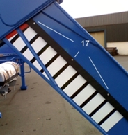
Position Magnetic strip with the screw holes facing upward (17) and screw in place. |
|
3 |
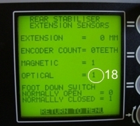
Test the retrofit by checking the display screen in Main Menu>View Sensor Values>Front (Rear) Stabiliser Extension Sensors. The Optical Sensor field should read 1. (18) (In future software upgrades the Optical label will be changed to Magnetic) Run the Stabiliser Extension in and out of the housing four or five times, checking the display each time to ensure the magnetic sensor is sensing correctly. |
|
Because the top screw attaching the encoder strip on the SB361 and SB401 remains inside the stabiliser housing even when fully extended, there are a few more steps involved in replacing it than for the SB330.
Step |
Action |
Notes |
|---|---|---|
1 |
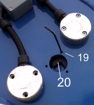
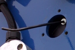
To undo the topmost screw, line up the screw with the hole as shown (19). (To line the underneath with the hole may take a bit of manipulating.) Put the Allen key through the hole and undo screw (19). You can see the castellated strip through the larger hole (20) Note: To fully undo screw, it may require an extra pair of hands pushing and holding back the stabiliser extension to make enough room while the screw is undone.
|
|
2 |
To remove the screw, extend the stabiliser a few cms more until the screw can be got at through the larger hole. Use the Allen key to lever it out. |
|
3 |
Continue as per the procedure above for the SB330. When attaching the magnetic encoder strip, reverse steps 1 and 2 of this procedure to attach the top screw then continue as per the SB330. |
|