Radios are factory set to AUTX mode as of November 2005.
SL0008 PDF File |
Version 2 |
SMARTlift |
27 August 08 |
Hetronic Radios operate between 433.1 MHz and 434.7750 MHz, which is divided into 32 channels. The radio will only operate on one channel at a time. If the radio encounters interference on the channel it is using then it will shut down the system as a safety precaution. This can present a repeated problem in certain locations, or even with certain trucks where the radio shuts down when the operator walks in front of the truck.
This information sheet will help to overcome these issues.
The Hetronic Radio can be set to three different addressing modes. The addressing modes are:
|
Radios are factory set to AUTX mode as of November 2005. |
If you need to set a radio to MANUAL mode contact the Steelbro Engineering Department.
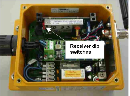
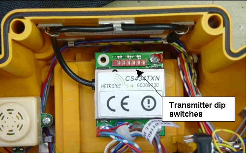
DIP switches in the Hectronic receiver and transmitter that need to be set are located as shown below.
|
|
Receiver DIP Switch Location |
Transmitter DIP Switch Location |
|
Before you set the DIP switches, ensure the key on the main control cabinet is in the OFF position and the battery is removed from the transmitter. |
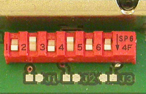
The arrow on the DIP switch block points towards the ON (1) position.
|
DIP Switches |
The above DIP switch illustration shows the following settings:
DIP Switch |
ON (1) or OFF (0) |
1 |
1 |
2 |
0 |
3 |
1 |
4 |
0 |
5 |
1 |
6 |
1 |
DIP switches 1, 2, and 3 select the AUTX mode. Theses switches should always be set to:
DIP Switch |
ON (1) or OFF (0) |
1 |
1 |
2 |
0 |
3 |
1 |
DIP switches 4, 5 and 6 select the frequency group. DIP switch 4 should always be set to:
DIP Switch |
ON (1) or OFF (0) |
4 |
0 |
Set DIP switches 5 and 6 to any of the following settings to select the frequency group:
DIP switch 5 |
DIP switch 6 |
Channels |
0 |
0 |
68, 58, 54, 52, 49, 41 |
0 |
1 |
67, 59, 55, 53, 47, 44 |
1 |
0 |
66, 64, 61, 57, 51, 43 |
1 |
1 |
65, 63, 60, 56, 50, 42 |
If you experience problems with one frequency group then select another group.
Do not set DIP switches 4, 5 and 6 to the following frequency groups as doing so will result in a weaker signal strength:
DIP switch 4 |
DIP switch 5 |
DIP switch 6 |
Channels |
1 |
0 |
0 |
38, 32, 28, 18, 10, 8, 5 |
1 |
0 |
1 |
37, 29, 25, 23, 17, 14, 4 |
1 |
1 |
0 |
36, 34, 31, 27, 21, 13, 3 |
1 |
1 |
1 |
35, 33, 30, 26, 20, 12, 2 |