S0022 Low Crane Base Repair on SB121 Sidelifters
S0022 PDF File
|
Version 1
|
Structural
|
07-07-05
|
The following is a procedure for repairing twisted and strengthening low crane bases on SB121 Sidelifters.
Removal of Crane required:
The repair of the SB121 low crane base requires the leg assembly and the arm crane assembly to be removed. This should be done by the following steps:
- Remove the lower leg on both the middle and rear crane by removing the L and H pins.
- Raise the bottom arms on both the middle and rear crane assemblies to allow the removal of the C pin. Then remove A pin, disconnect hydraulics and remove arm assembly.
- Remove the legs lower/raise cylinder and remove the bottom arm lift cylinder.
Repair to Low crane base Stage 1:
The crane base requires straightening and strengthening using the following instructions and dimensions:
- Remove on the crane base part S2-32375 (Plate diaphram arm end), which is the sloped plate in Figure 1. This plate needs to be removed, without damaging any other plates it is welded to. The surrounding plates, that S2-32375 was welded to, need to be tidied up so that their surfaces are flat.
- Straighten pressings. The crane base pressings must conform to the dimensions and tolerances allowed in Figure 2. The H pin must be within the perpendicular and parallel tolerances stated in Figure 2. If these dimensions and tolerances cannot be meet then the Sidelifter repair must be done in accordance with stage 2. Note that the dimensions in parenthesis are check dimensions and have a general tolerance of ±2.0mm.
- When straightened check the measurements of the twistlocks and centers of the crane base pressings as stated in Figure 3.
- Once pressing centres are correct and pressings are straightened, cut out of 50 x 10 Flat bar, Grade 250, two pieces 442mm long with a 50° angle on the end of it as pictured in Figure 4. These parts need to be tacked into position using the dimensions in Figure 5, and welded to weld specifications WP-34970.
- Cut out of Grade 350 Plate, 08mm, part S2-32375. Tack this part into the crane base according to Figure 6. Weld part S2-32375 to weld specifications WP-34970 and WP-34851.
- Recheck dimensions in Figure 2 and Figure 3.
Repair to Low crane base Stage 2:
Carry out this section of the repair when straightening of the crane base pressings cannot conform to the requirements in Figure 2, Section 2 in Stage 1.
- Straighten crane base pressings to the straightness and flatness requirements in Figure 2.
- Cut out of the assembly, the A pin bosses. The hole cut out should be greater than Ř100mm but still kept as small as possible.
- Make up 2 bosses as to Figure 7. These bosses are made out of AISI 1018/1020 round bright bar.
- Position the bosses to the stated dimensions in Figure 8. Weld in the bosses to Figure 8 and weld specifications WP-34970.
- Line bore to drawing S2-32366.
- Proceed to Steps 3 in Stage 1 of repair.
Bottom Arm checks:
Because of the extent of the damage the bottom arm must be checked. The following measurements must be checked.
- Check the straightness of the arm shown in Figure 9.
- Check the perpendicularity and parallelism of the A pin boss as per Figure 10 and the offset for the A & E pin clevis plates.
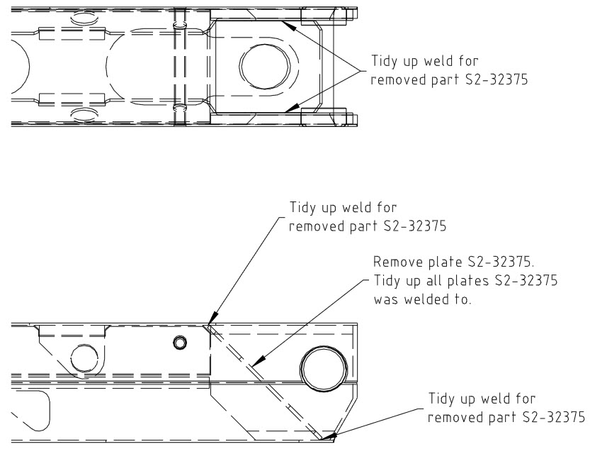
Figure 1: Removal of part S2-32375
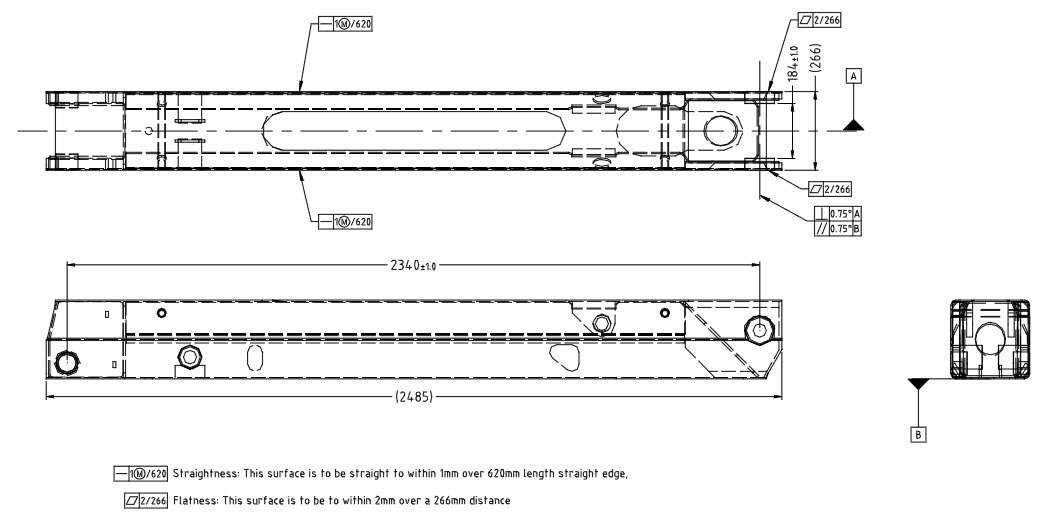
Figure 2: Straightness, flatness, perpendicularity, parallelism and dimension requirements.
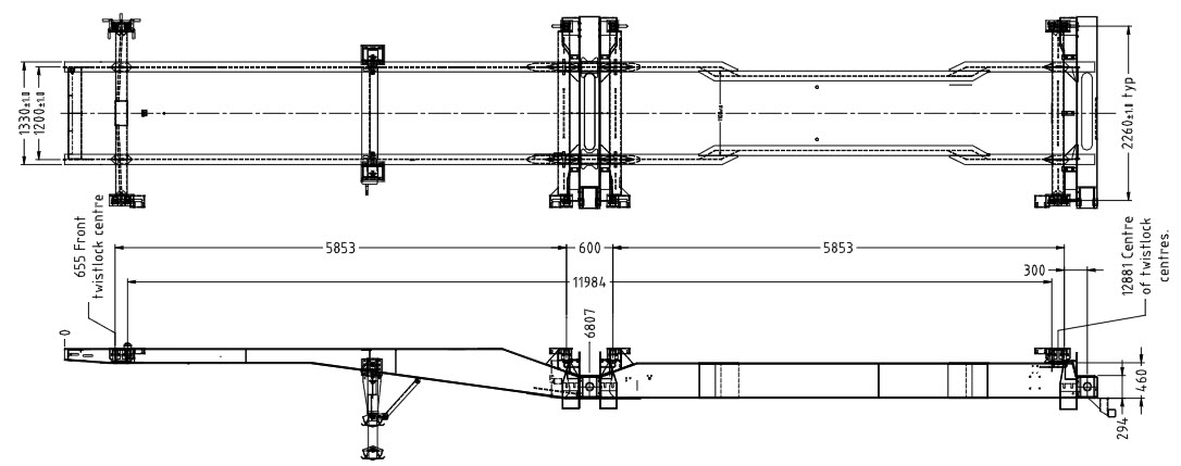
Figure 3: Check measurements required along chassis.
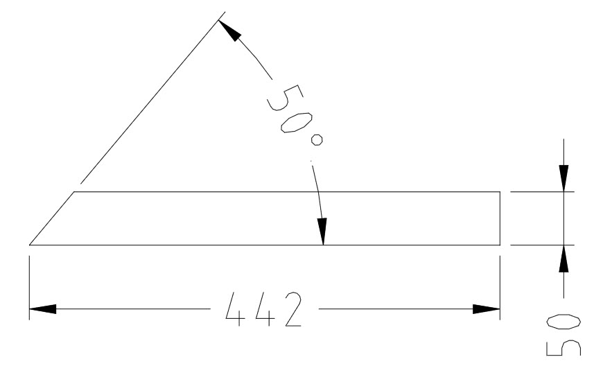
Figure 4: Reinforcement bar required made out of Grade 250 Flat bar 50 x 10.
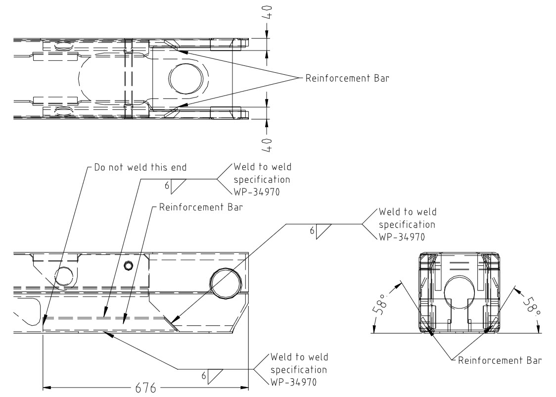
Figure 5: Requirements for welding in reinforcement bars.
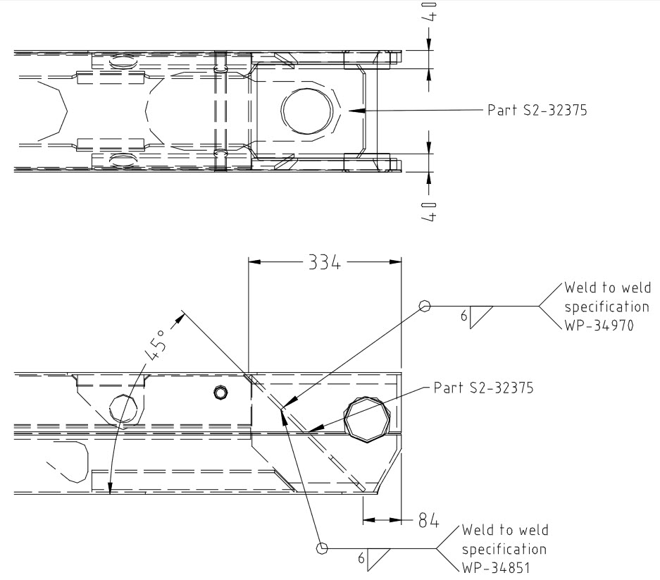
Figure 6: Requirements for welding in new part S3-32375
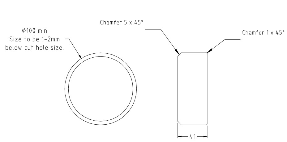
Figure 7: Boss, required to be cut from Bright round bar AISI 1018/1020
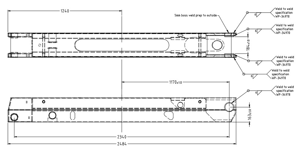
Figure 8: Requirements for welding in new bosses
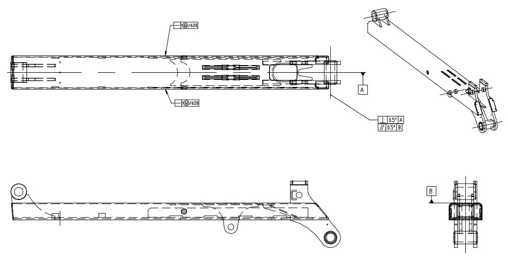
Figure 9: Bottom arm checks required.