S0017 PDF File |
Version 2 |
Structural |
17-08-04 |
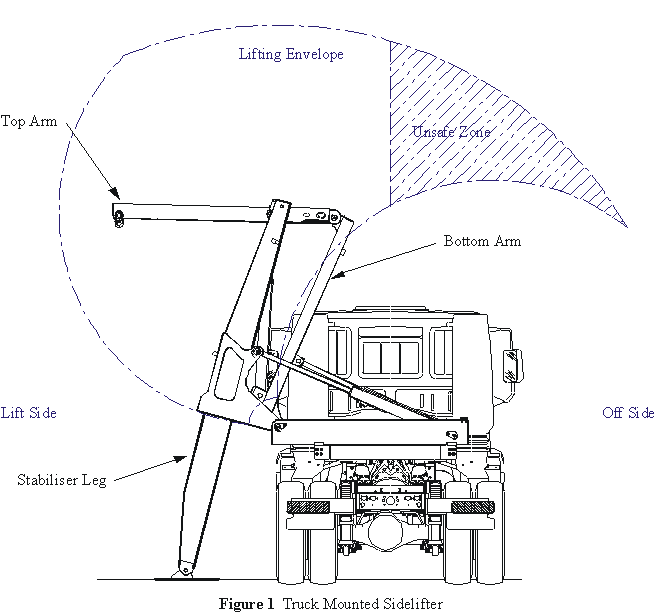
When operating a Steelbro Crane Set, the stability of the crane is primarily governed by three factors:
These can each be affected by other factors, i.e. the deck height limits how far out the stabiliser foot can reach when placed on the ground; the suspension lash effects the contribution of un-sprung mass to the effective tare.
When the cranes are not fitted with offside stabiliser legs, positioning the load past the centre of the deck in the offside direction can lead to instability.
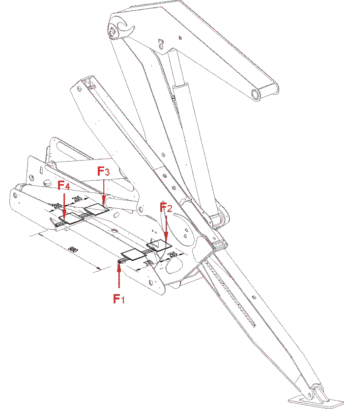
There are two extreme load conditions subject to the crane supports.
Model |
SB121 |
|||||||
|
Condition |
1 |
2 |
|||||
Load on Support |
F1x |
-44 kN |
140 kN |
|||||
F1y |
39 kN |
168 kN |
||||||
F2x |
18 kN |
-114 kN |
||||||
F2y |
-91 kN |
-134 kN |
||||||
F3y |
-27 kN |
17 kN |
||||||
F4y |
-27 kN |
17 kN |
||||||
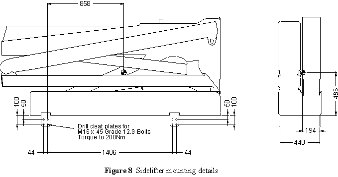
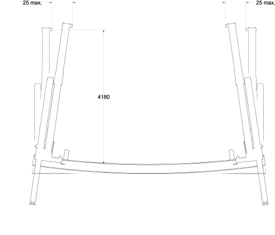
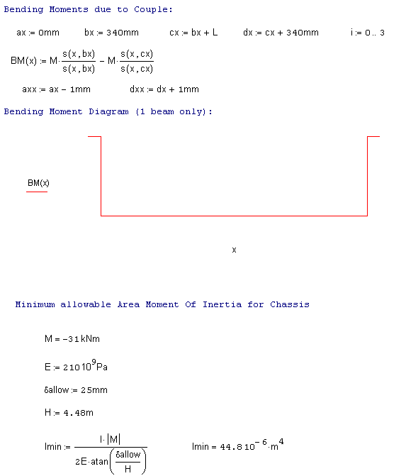
The design of the support frame or chassis is required to be stiff enough to prevent excessive deflection at the lifting pin (G Pin) on the crane. As long as the deflection at each crane due to the loads specified above, does not exceed 25mm at a height of 4180 above the support flange, then the correct operation of these units will be ensured.
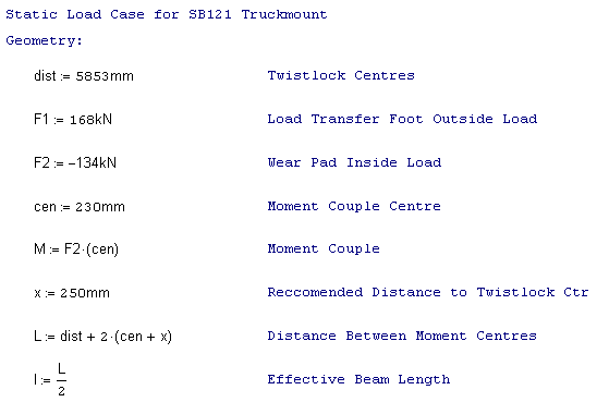
The load distribution for a typical truck mount is as shown below:
The majority of truck manufacturers recommend that the sub-frame be attached to the chassis in such a way that the original bending and torsional characteristics of the vehicle are retained. This does create some conflict with the requirement for the two cranes to maintain alignment and minimise rolling of the chassis during the lifting process.
As the exact arrangement of supports will vary from installation to installation the following calculation has been carried out with assumptions i.e. consider the loads to be taken solely by one beam. The most critical aspect identified for proper crane operation is the amount of deflection allowed by the support frame/chassis. The following diagram considers only the opposing moment couples generated by the rolling of the cranes towards each other. From these we can determine the minimum chassis strength required to resist deflection if not taking axle supports into account.
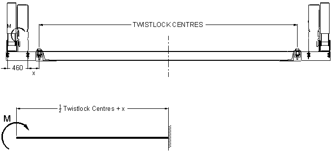
Figure 6 Free body diagram for simplified truck chassis
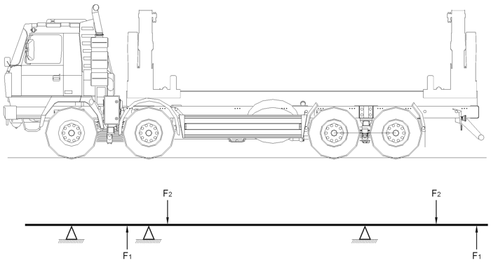
Figure 7 Free body diagram for typical truck chassis
Considering only one beam on the lift side of the truck to be resisting the moment couple, this will give a conservative stiffness requirement
.
Model |
SB121 |
I (m4) |
44.8 x 10 - 6 |
Table 2 Recommended Minimum Area Moment of Inertia Values, for 20 Foot Supporting Chassis
|
Note this calculation does not account for the horizontal loads. These would have less effect on the chassis & sub-frame loading due to the spacing of the rails. But these need to be considered when detailing the attachment of cleat plates, etc. |
Model |
|
SB121 |
1500 kg |
Table 3 Approximate Sidelifter Tare Weights
(per crane only - no fittings/subframe included
To ensure correct operation of the cranes, it is important that the support frame is parallel to the ground when installed on the vehicle.