S0014 PDF File |
Version 1 |
Structural |
01-07-04 |
The hydraulic components on the Tractor unit consists of the following:
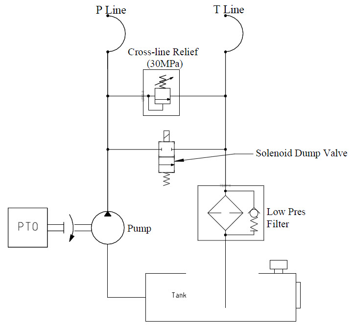
The truck speed control is required to be fitted with a governor that can be set to a particular rev range when the PTO pump is engaged. This will ensure that the correct oil flow can be achieved for the appropriate model (refer to model specific details). A cross-line relief and solenoid dump valve should be incorporated into the circuit. Some models of pump are fitted with either or both of these devices. This is acceptable provided that the cross-line relief remains active in the circuit at all times.
Figure 1: Schematic for Typical PTO Pump Supply Circuit
|
Take precautions when disconnecting hydraulic tubing and hoses to ensure that no hydraulic pressure has been retained in the line when the power supply to the system has been switched off. |
The electrical connection of the Sidelifter controls to the truck is made with a seven-wire interface:
Black |
Earth for all controls and lights. |
Blue |
Output from the container position optical sensor. |
Grey |
Output for throttle control signal. |
Red |
Supply to the control system via a 20amp relay (not supplied). |
Pink |
Output to emergency stop. |
White/Yellow |
Supply to the container position optical sensor. |
Orange |
Supply to the Work Lamps via a 20amp relay (not supplied). |
This may be wired directly into the truck or connected via an S Type Plug. The standard voltage for all inputs and outputs is 24v, but may be set up for 12v systems where appropriate. Steelbro recommends the use of the S type plug to avoid confusion with other plugs.
Most installations will require two control switches in the cab of the truck.
Three output signals are available for feedback to the truck.
|
The emergency stop is a critical safety function of the PTO driven sidelifter. In the emergency condition the hydraulic power source must be effectively removed. Steelbro highly recommends the set-up described in figure 1. Use of a pump such as a parker F1 with BPV-F1-81 bypass valve, provided it is wired correctly, is an effective way of achieving this. |
PTO Details: |
|
Oil tank volume: minimum |
200 L |
Low pressure filter flow: |
230 l/min |
Low pressure filter filtration (absolute): |
25 micron |
Flow rate |
120 l/min |
Pressure |
280 bar |
Truck Governor |
Control range / All range |
|
|
Electrical: |
|
Current Draw @ 12V (Standard Night Lights 2 lights) |
15 A |
Current Draw @ 12V (Special Night Lights 6 lights) |
23 A |
Control System voltage: |
12 or 24 V |
|
|
