S0013 print pdf |
Version 1 |
Structural |
01-07-04 |
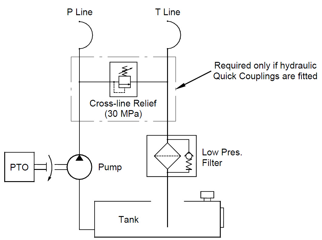
The hydraulic components on the Tractor unit consist of the following:
The truck speed control is required to be fitted with a governor that can be set to a particular rev range when the PTO pump is engaged. This will ensure that the correct oil flow can be achieved for the appropriate model (refer to model specific details). If the hydraulic supply is to be fitted with Quick Coupling connections i.e. cranes are to be demountable; the additional valve shown in Figure 1 will be required to protect the pump from over pressurising. Otherwise installing a pump with an integrated bypass relief will achieve this.
Figure 1 Schematic for Typical PTO Pump Supply Circuit
|
Take precautions when disconnecting hydraulic tubing and hoses to ensure that no hydraulic pressure has been retained in the line when the power supply to the system has been switched off. |
The electrical connection of the Sidelifter controls to the truck is made with a seven-wire interface:
Black |
Earth for all controls and lights. |
Blue |
Output from the container position optical sensor. |
Grey |
Output for throttle control signal. |
Red |
Supply to the control system via a 20amp relay (not supplied). |
Pink |
Output to emergency stop. |
White/Yellow |
Supply to the container position optical sensor. |
Orange |
Supply to the Work Lamps via a 20amp relay (not supplied). |
This may be wired directly into the truck or connected via an S Type Plug. The standard voltage for all inputs and outputs is 24v, but may be set up for 12v systems where appropriate.
Most installations will require two control switches in the cab of the truck.
Three output signals are available for feedback to the truck.
PTO Details: |
|
Oil tank volume: minimum |
200 L |
Low pressure filter flow: |
230 l/min |
Low pressure filter filtration (absolute): |
25 micron |
Flow rate |
120 l/min |
Pressure |
280 bar |
Truck Governor |
Control range / All range |
|
|
Electrical: |
|
Current Draw @ 12V (Standard Night Lights 2 lights) |
15 A |
Current Draw @ 12V (Special Night Lights 6 lights) |
23 A |
Control System voltage: |
12 or 24 V |
|
|
The hydraulic pipes should be run to layout drawn in Figure 2 and shown in Figure 3 and Figure 4. This layout performs well in the harsh conditions that the hoses will be put through. The circuit consists of the hydraulic hoses running from the hydraulic pump along the bottom of the tractor chassis until the hoses are behind the fifth wheel. The hoses are then looped to the top chassis. From this position they run underneath the fifth wheel and get connected to the Hydraulic hose swing arm. The swing arm keeps the hoses in a rigid state and allows the hoses to swing through the required arch without rubbing and catching on the trucks chassis and accessories.
Quick releases are attached to the end of this swing arm. Hydraulic hoses, looped from the trailer via an arm, have the other halves of the quick releases attached to them.
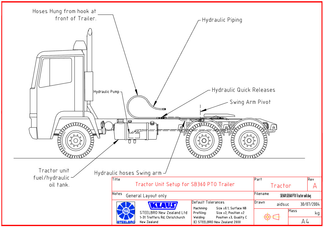
Figure 2: Drawing showing general Layout.
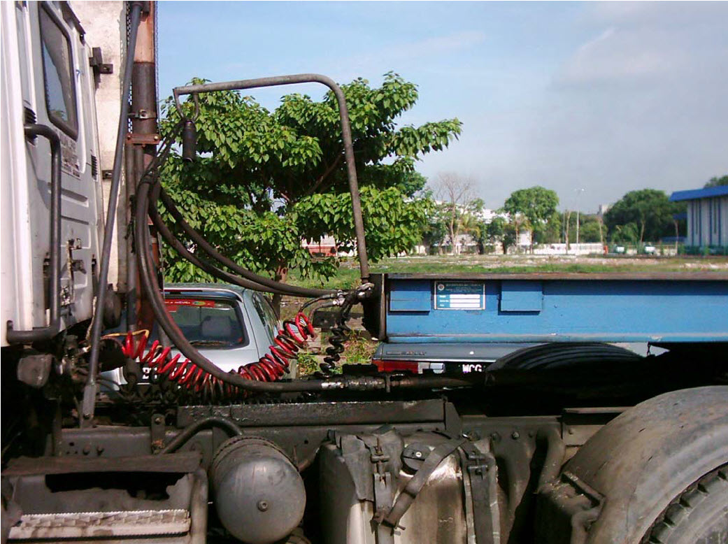
Figure 3: Photo showing looping of Hydraulic hoses to quick releases.
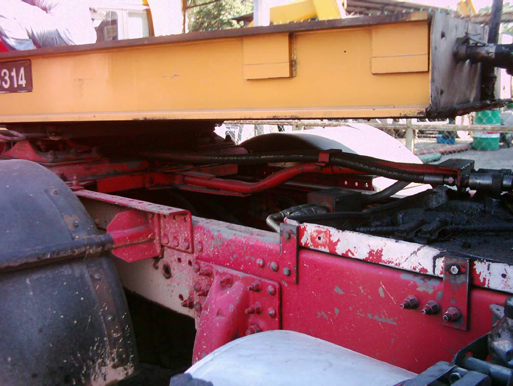
Figure 4: Photo showing Hydraulic hose swing arm.