S0001 MK6 Rack and Pinion Adjustment
S0001 PDF File
|
Version 1
|
Structural
|
8-7-98
|
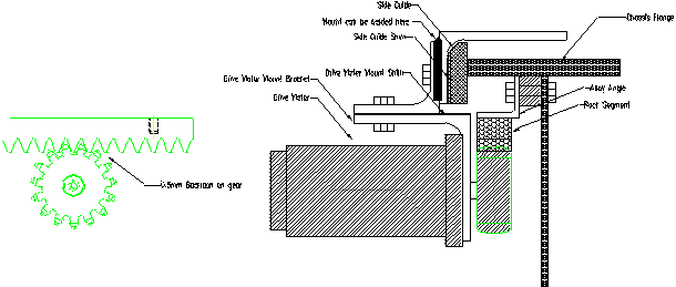
Procedure for adjusting the rack and pinion module traverse on a MK6
To enhance the service life of the rack and pinion shift system the mesh between rack and pinion should be inspected on a regular basis. The amount of backlash is governed by the amount of wear in the crane base wear pads and the shims fitted to the motor mount.
Inspect the rack section for wear. Note that the wear pattern should be as per the following. Replace any damaged rack segments with genuine spare parts.

To adjust the rack and pinion to the correct 0.5mm backlash tolerance carry out the following:
- Inspect the crane base wear pads for excessive wear. If the pads are worn (less than 7mm of pad material remaining) replace the pads as per separate instruction.
- Check motor mount bracket and alloy angle for any distortion and correct if necessary.
- On early machines the motor mount bracket assembly was bolted to the module base support angle. This can be welded to minimise distortion
- Check the side movement of the module (crane base) and adjust the side guide wear pads with shims to obtain a maximum wear pad clearance to flange of 2mm.
- Adjust the backlash between rack and pinion by adding or removing drive motor mount shims so as to obtain a maximum backlash of 0.5mm.
- Check all bolts are tight and test unit by running the crane base over its full travel and inspecting the backlash at random points along the chassis.

|
To enhance the life of the rack segments it is advisable to change or rotate the racks so that the rack at the start of crane base movement is moved to a more central position along the chassis where the forces are lower.
|