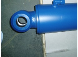
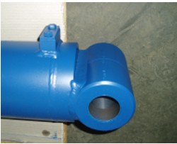
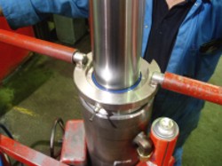
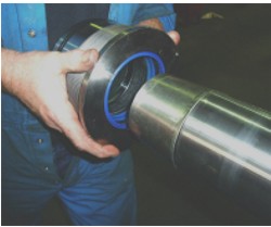
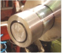
There is an identification groove in the rod and base.
5 Nov 2008 PDF File |
Hydraulics |
Version 1 |
|
There is an identification groove in the rod and base. |
|
Model |
Part Number |
Description |
SB300 |
HC-25806 |
Cylinder Hyd Bottom Lift |
|
HC-25807 |
Cylinder Hyd Top Lift L/H |
|
HC-25808 |
Cylinder Hyd Top Lift R/H |
|
HC-25805 |
Cylinder Hyd Stabiliser Extn |
|
HC-25809 |
Cylinder Hyd Stabiliser Tilt |
|
|
|
SB330 |
HC-22565 |
Cylinder Hyd Traverse |
|
HC-31629 |
Cylinder Hyd Bottom Lift |
|
HC-25807 |
Cylinder Hyd Top Lift L/H |
|
HC-25808 |
Cylinder Hyd Top Lift R/H |
|
HC-25805 |
Cylinder Hyd Stabiliser Extn |
|
HC-25809 |
Cylinder Hyd Stabiliser Tilt |
|
|
|
SB360 |
HC-31628 |
Cylinder Hyd Bottom Lift (Type 2) |
|
HC-25801 |
Cylinder Hyd Bottom Lift (Metric Type 1) |
|
HC-25802 |
Cylinder Hyd Top Lift |
|
HC-25803 |
Cylinder Hyd Top Lift Ext Reach |
|
HC-25805 |
Cylinder Hyd Stabiliser Extn |
|
HC-25804 |
Cylinder Hyd Stabiliser Tilt |
|
|
|
SB361 |
HC-32283 |
Cylinder Hyd Bottom Lift |
|
HC-32279 |
Cylinder Hyd Top Lift |
|
HC-32287 |
Cylinder Hyd Stabiliser Extn |
|
HC-32285 |
Cylinder Hyd Stabiliser Tilt |
|
|
|
SB401 |
HC-32283 |
Cylinder Hyd Bottom Lift |
|
HC-32281 |
Cylinder Hyd Top Lift |
|
HC-32287 |
Cylinder Hyd Stabiliser Extn |
|
HC-32285 |
Cylinder Hyd Stabiliser Tilt |
|
Figure 1 |
|
Figure 2 |
|
Figure 3 |
|
Figure 4 |
|
Figure 5 |
|
Figure 6 |
|
Figure 7 |
|
Figure 8 |
|
Figure 9 |
|
Figure 10 |
|
Figure 11 |
|
Figure 12 |
|
Figure 13 |
|
Figure 14 |
|
Figure 15 |
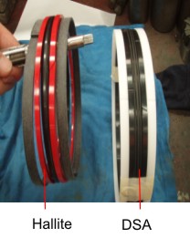
Piston Seals |
|
SB360 SB330 SE400
|
|
SB361 |
|
|
|
|
|
Gland Seals |
|
SB360 SB330 SE400 |
|
SB361 |
|
|
|
Rod Wiper |
|
SB360 SB330 SE400 SB361 |
|
|
|
Wear Rings |
|
SB360 SB330 SE400 SB361 |
|
|
Figure 16 |
|
Figure 17 |
|
Figure 18 |
|
Figure 19 |
|
Failure to apply the correct torque settings could result in severe damage to the Sidelifter or to personnel. |
Bore size |
Rod size |
Thread |
Torque Nm |
8.0" |
4.0" (101.6) |
3.75"12 TPI UNF |
24,232 Nm |
7.0" |
3.5" (88.9) |
2 15/16" 16 TPI UNF |
14,838 Nm |
6.0" |
4.0" (101.6) |
2 15/16" 16 TPI UNF |
10,100 Nm |
6.0" |
3.5" (88.9) |
2 15/16" 16 TPI UNF |
11,621 Nm |
5.0" |
2.5" (63.5) |
1 15/16" 16 TPI UNF |
5,147 Nm |
4.0" |
3.0" (76.2) |
1 15/16" 16 TPI UNF |
1,893 Nm |
4.0" |
2.5" (63.5) |
1 15/16" 16 TPI UNF |
2,599 Nm |
2.5" |
1.5" (38.1) |
1 1/8" 12 TPI UNF |
385 Nm |
|
Figure 20 |
|
Figure 21 |
|
Figure 22 |
|
Figure 23 |
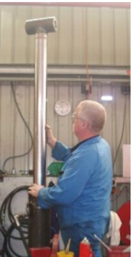
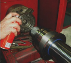
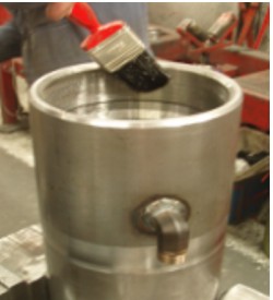
To ensure there are no oil leaks from welds, port and seals on all Steelbro cylinders.
All Steelbro cylinders are to be tested for hydraulic oil leaks. Follow this testing procedure:
Note: only on bottom lift cylinder.
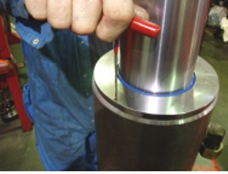
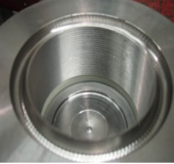
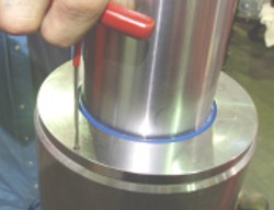
O-ring seal |
|
Bypass hole. O-ring sealing face |
|