H0024 PTO Return Line Pressure Protection
19 Dec 2007 PDF File
|
Hydraulics
|
Version 2
|
|
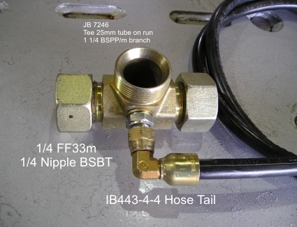
- Drill and tap a hole to suit a Ľ BSP nipple in the return line 25mm tube tee Part number JB7246
- Fit Ľ BSP nipple into the 25mm tee using loctite hydraulic sealant. Part number 1/4FF33M
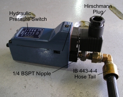
- Fit Ľ BSP nipple into hydraulic pressure switch using loctite hydraulic sealant. Pressure switch Part number EL-33795
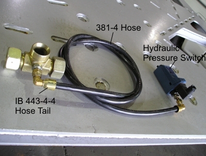
- Fit hydraulic pressure switch to the Sidelifter chassis
- Cut hydraulic pressure hose to length and swage. Hose type 381-4
- Fit a dump cartridge to the P.T.O pump on the tractor unit
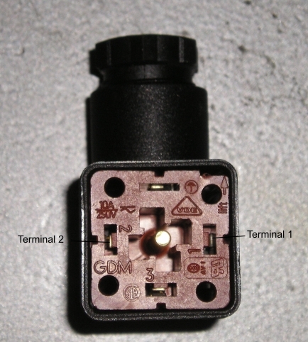
- Run a power feed to the hydraulic pressure switch which may come from the Sidelifter power feed at either the back of the front coupling plug or the main control box. Connect to terminal 1
- Run a feed wire from terminal 2 on the hydraulic pressure switch to the auxiliary terminal on the trailer lighting plug and through to the positive side of the P.T.O dump cartridge coil
- Fit an on/off ball valve and pressure gauge into the return line between the hydraulic pressure switch and the quick release coupling. (Remember to remove it afterwards)
- Set the relief pressure on the hydraulic pressure switch to around 8 bar.
- With the P.T.O running slowly close the ball valve while watching the pressure gauge. The hydraulic pressure switch should cut the power to the dump valve when it reaches 8 bar.
- If the system tests ok reset the hydraulic pressure switch to 20 bar and retest.