G0008 Commissioning Procedures for Truck-mount Cranes
G0008 print pdf
|
Version 4
|
General Info
|
21 June 2010
|
PTO Driven Hydraulic System
The hydraulic system consists of the following:
- PTO pump fitted to the truck (not supplied)
- Hydraulic oil tank with low pressure filter (not supplied)
- High pressure supply and low pressure return lines
- High pressure filter
- Two banks of Danfoss proportional control valves
- Four hydraulic cylinders fitted with double check valves operating the stabiliser legs
- Two hydraulic cylinders fitted with single over-centre valves operating the top lifting arms
- Two hydraulic cylinders fitted with double over-centre valves operating the bottom arms
- A solenoid operated dump valve connected to the load sense line
- A hydraulic pressure gauge
System Control
The system is controlled by a cable or optional radio remote. These have identical ergonomics consisting of a pair of two axis joysticks, a function selector switch, a high / low speed selector switch and an emergency stop button.
Required Set-up of Truck and Pump
The truck speed control is required to be fitted with a governor that can be set to a particular rev range when the PTO pump is engaged. The oil tank should be fitted high and as close as practical to the PTO pump. This will ensure that the correct oil flow can be achieved for the appropriate model (refer to model specific details). All hoses to and from the tank, fittings, and sight gauge must be protected and positioned well clear of wheels to avoid possible damage from tyre blowouts and stones being flicked up from the wheels. The sight gauge should be clearly readable. If the fuel tank must be moved, to cater for the hydraulic tank, then ensure the tank is positioned well clear of suspension brackets and bolts.
If the hydraulic supply is to be fitted with Quick Coupling connections i.e. cranes are to be demountable; the cross-line relief valve shown in Figure 1 will be required to protect the pump from over pressurising. The solenoid dump valve is required for all installations. Otherwise installing a pump fitted with either or both of these devices will be acceptable as long as the cross-line relief remains active in the circuit even when the unit has been uncoupled.
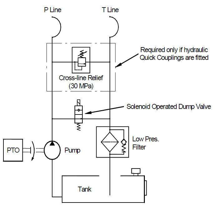
Figure 1: Schematic for Typical PTO Pump Supply Circuit
|
System Operation
High pressure oil is supplied from the PTO driven pump to the high pressure filter, beyond this filter it is divided and supplied to the front and rear control valves. These valves are connected to each other with a load sensing (LS) line. This helps to maintain synchronisation of the two cranes when unequal loads are handled. Fitted into the LS line is a solenoid operated dump valve. When the valve is in the de-energised condition LS oil is dumped to tank. When the valve is energised the LS line is blocked to tank enabling the hydraulic system to operate. A hydraulic gauge is fitted into the LS line indicating hydraulic system pressure.
The crane control valves are Danfoss PVG 32 proportional type, signalled from the joysticks for directional control. High or low speed can be selected at the remote control. For Sidelifters with Series 3A electrics, when "Low Speed" is selected the joystick signal passes via an electronic hydraulic flow (EHF) control and the function speed is reduced by 50% allowing fine control under heavy and difficult loading conditions. For Sidelifters with the SMARTlift electrical system, when "Low Speed" is selected SMARTlift reduces the function of the speed by 50% allowing fine control under heavy and difficult loading conditions. The low speed function only applies to the lifting arms. The stabiliser legs are always in high speed irrespective of the position of the high /low speed selector switch.
Note: Take precautions when disconnecting hydraulic tubing and hoses to ensure that no hydraulic pressure has been retained in the line when the power supply to the system has been switched off. The check valves fitted to the hydraulic cylinders will trap pressure and may eject oil at high speed when being removed.
Setting Up the System
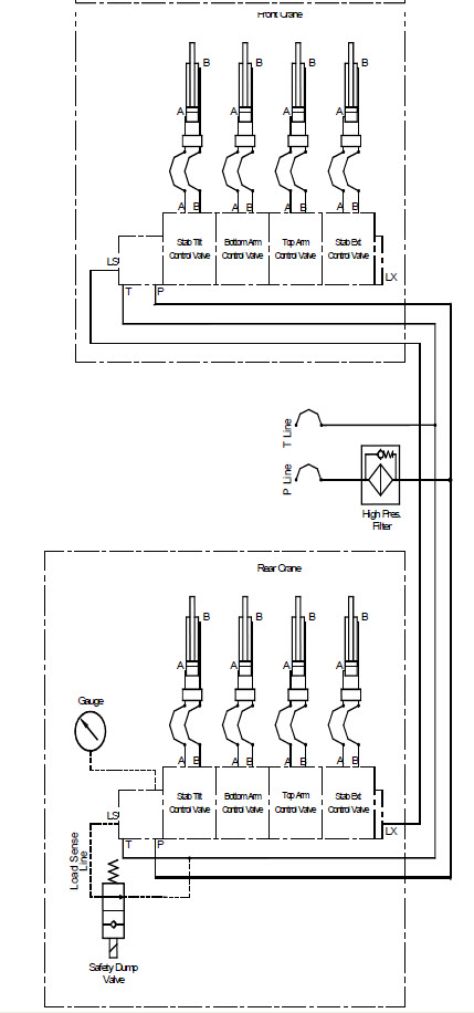
The schematic shown in Figure 2 is for a set of typical truck-mount cranes. Each crane has three hydraulic connections: one 1/2" Supply Line; one 3/4" Return Line; one 3/8" Load Sense Line. These are run to the supply filter in close proximity to the truck PTO pump, and the return filter mounted on the tank. The gauge and dump valve are both located on the rear crane base.
Note that the 3/8" hose running to the rear LX connection on the Danfoss valve bank will require a 1/4" hose tail due to the limited space around the fitting.
|
Figure 2: Hydraulic Schematic for Typical Crane Installation
|
Electrical Controls
SMARTlift Electrical System
Wiring Diagrams:
Model
|
Drawing Number
|
SB361, SB401
|
EL-37781
|
SB200, SB300, SB330
|
EL-37779
|
The electrical system consists of the following:
- A main junction box mounted to the truck chassis, normally on the non-lifting side
- A display junction box mounted to the truck chassis, normally on the rear end
- Two, crane mounted junction boxes
- One radio remote control and optional cable remote control
The system supplied will have been tested and operated during the factory testing and adjustment of the cranes.
The electrical connection of the Sidelifter controls to the truck is made with a seven-wire interface:
Colour
|
S-Plug
|
PCB JP9
|
Wire Size
|
Description
|
Black
|
Pin-1
|
S1
|
3.0mm2
|
Earth. For all controls and lights
|
Blue
|
Pin-2
|
S2
|
1.25mm2
|
Output. Optical sensor (container position) light in the truck cab
|
Grey
|
Pin-3
|
S3
|
1.25mm2
|
Output. Engine throttle (throttle solenoid if option is feed from truck cab
|
Red
|
Pin-4
|
S4
|
3.0mm2
|
"E" enclosure (sidelifter) system power 'ON' (to relay triggered by PTO switch)
|
Pink
|
Pin-5
|
S5
|
1.25mm2
|
Output to PTO dump solenoid (probably mounted in chassis)
|
White/Yellow
|
Pin-6
|
S6
|
1.25mm2
|
Optical container sensor power (from switch in cab)
|
Orange
|
Pin-7
|
S7
|
3.0mm2
|
Permanent power supply from truck via 20 amp fuse (not supplied)
|
This may be wired directly into the truck via 17mm conduit, or connected via an S-Type Plug for demountable cranes. The standard voltage for all inputs and outputs is 24V, but may be set up for 12V systems if required.
The "E" enclosure has been wired to give two options from where the throttle and PTO dump can be run. Both are wired to JP9 S3 and S5 "E" enclosure. The unused circuits should be removed.
- Throttle brown 2-core or grey (JP9 S3)
- PTO dump brown 2-core or pink (JP9 S5)
The two 2-core cables that have been added to the "E" enclosure, marked "throttle" and "PTO dump", use these wires if throttle wiring and PTO dump is located in the chassis, this is the most likely scenario. If one or both are not required, please remove and blank off holes with supplied plugs.
The grey and pink wires run via a 17mm conduit to the truck cab. If these are not used disconnect from JP9 and fold back neatly.
Most installations will require two control switches in the cab of the truck:
- The main system start/stop switch turns the system on and off. This would typically activate a relay that supplies power (red) to the control system and engages the PTO pump (other). This relay should be earthed through the 'handbrake on' contacts to ensure the system cannot be activated while the vehicle is in motion.
- A container detection switch may be required to activate the optical sensor (white/yellow). Otherwise this can be wired into the reversing lamp circuit of the vehicle so that it becomes automatically active when the truck reverses.
Three output signals are available for feedback to the truck:
- The container position output (blue) will provide a signal when the optical sensor has sighted an object within 500mm from the side of the vehicle. This should be wired to a signal lamp in the cab of the truck to alert the driver when the front twistlock passes the corner of the container, to assist with correct positioning of the vehicle.
- The output for the Emergency Stop (pink) will provide a continuous signal all the time that the crane control system is active. When the emergency stop is triggered on the remote control or if a tank line pressure switch (optional) is activated, this will cease. This should be wired to the dump solenoid on the Sunfab PTO pump.
- The throttle control signal (grey) is activated whenever a movement is made with the joysticks on the remote. This can be used on some vehicles to signal the engine management system to change engine speed. The signal continues for three seconds after the joysticks are released to allow for smoother start-stop operations. This can reduce the heating of hydraulic oil, as the PTO can be set to run at a lower idle speed. Most vehicles have the PTO operating speed set when the main system switch is activated.
Series 3A Electrics
The electrical system consists of the following:
- A main junction box to be mounted onto the truck
- Two crane mounted junction boxes
- One cable remote control and/or radio remote control (optional)
The system supplied will have been tested and operated during the testing and adjustment of the cranes. The main control box should be placed in an easily accessed position on the truck. Often these are fitted to the rear of the chassis or support frame so that it is in a good position for the cable remote to be plugged into. This is less important if using a radio remote control.
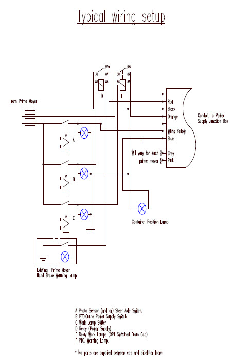
The electrical connection of the Sidelifter controls to the truck is made with a seven-wire interface (Figure 3):
1
|
Black
|
Earth for all controls and lights
|
2
|
Blue
|
Output from the container position optical sensor
|
3
|
Grey
|
Output for truck engine throttle control signal
|
4
|
Red
|
Supply to the control system via a 20amp relay (not supplied)
|
5
|
Pink
|
Output to emergency stop
|
6
|
White/Yellow
|
Supply to the container position optical sensor
|
7
|
Orange
|
Supply to the Work Lamps via a 20amp relay (not supplied)
|
This may be wired directly into the truck or connected via an S Type Plug for demountable cranes. The standard voltage for all inputs and outputs is 24v, but may be set up for 12v systems where appropriate.
Most installations will require three control switches in the cab of the truck.
- The main system start/stop switch turns the system on and off. This would typically activate a relay that supplies power (red) to the control system and engages the PTO pump (other). This relay should be earthed through the 'handbrake on' contacts to ensure the system cannot be activated while the vehicle is in motion.
- A Work Lamp (or night lights) switch is required to activate the relay supplying power (orange) to the crane mounted night working lights.
- A container detection switch may be required to activate the optical sensor (white/yellow). Otherwise this can be wired into the reversing lamp circuit of the vehicle so that it becomes automatically active when the truck reverses.
Three output signals are available for feedback to the truck
- The container position output (blue) will provide a signal when the optical sensor has sighted an object within 500mm from the side of the vehicle. This should be wired to a signal lamp in the cab of the truck to alert the driver when the front twistlock passes the corner of the container, to assist with correct positioning of the vehicle.
- The output for the Emergency Stop (pink) will provide a continuous signal all the time that the crane control system is active. When the emergency stop is triggered on the remote control or on the front of the control cabinet, this will cease. This should be wired to the ignition (electronic or otherwise) to stop the engine when this signal is no longer present.
- The throttle control signal (grey) is activated whenever a movement is made with the joysticks on the remote. This can be used on some vehicles to signal the engine management system to change engine speed. The signal continues for three seconds after the joysticks are released to allow for smoother start-stop operations. This can reduce the heating of hydraulic oil, as the PTO can be set to run at a lower idle speed. Most vehicles have the PTO operating speed set when the main system switch is activated.EL-37779
|
Figure 3: Typical Wiring Setup
|
Chassis Loading & Finishing
- Check specification for appropriate model.
- Ensure truck hydraulics are set up per the hydraulic schematic for the appropriate model.
- Correct displacement pump is fitted for required flow at desired running speed of truck. Pressure rating and relief settings for this pump correspond to recommendations.
- Correctly sized oil tank is fitted and plumbed to ensure uninhibited suction from bottom of tank.
- Hydraulic pipework is run down the support frame or truck chassis to both crane positions.
- Ensure hydraulic hoses cannot rub on each other or any other object and do not pass over battery or air cleaner access. Orientate elbow fittings square to horizontal or vertical wherever possible.
- Tie valve handles open with cable ties or similar to prevent unintentional shutting-off.
- Ensure support frame or truck chassis mountings have been set up for the appropriate model, as per Steelbro Installation Advice for Trucks.
- Ensure Stop Blocks are not fitted to the truck support frame and the Load Transfer Blocks are not fitted to the crane.
- Load modules onto the supports and position cranes were required to ensure that the required positions can be achieved. Check twistlock spacings are correct both longitudinally and diagonally when in place.
- Fit the required Load Transfer Blocks to the cranes with six M8x80 cap screws and shims to ensure a close fit to the underside of the support flanges. A maximum clearance of 1mm is recommended. If the modules are to be non-sliding then this can be a non-clearance fit.
- The Side Guide Wear Pads are typically set up for the standard 1100mm or 1150mm width to outside of support flanges. These can be shimmed to accommodate excessive (> 2mm) variation in the fabricated support frame.
- Fit the Inside Stop Blocks and ensure that each crane is pushed forward against them. Recheck twistlock spacings both longitudinally and diagonally. (Note that the tolerance on the container interface dimensions is typically ? 6mm longitudinally, ? 3mm transversely and ? 9mm diagonally)
- Fit the Outside Stop Blocks on the top of the support plate with a minimal gap (<1mm) between the block and the crane base. These are each bolted down with four M12x50 cap screws.
Connect crane supply hoses to the modules:
- Run electrical control cables from control/remote box to each of the individual crane junction boxes.
- Once all hydraulics have been connected fill the oil tank to 3/4 full.
Pre-commissioning Checks
Prior to running the new Sidelifter the following checks should be made:
- Examine the Sidelifter, checking that the specification is as ordered
- Check all exposed components (lights, handles, chains etc) have not been damaged during delivery or installation
- Check the operation of the offside batten poles - if fitted
Check the alignment of the optical offside detection sensors - if fitted.
Check the correct alignment of the optical container position sensor - if fitted.
- The chain slings have been matched to the cranes. If a tag has been fitted to the slings, check that the serial number matches that of the cranes, and the SWL is more than half the SWL of the appropriate model, i.e. SWL for SB300 slings are greater than 15000kg each.
It is recommended that the start-up procedure be carried out without the chains fitted.
- Check cylinder rods for damage or excess paint.
- Correct operation of all twistlock mechanisms.
- Check all greasing points have been greased, and the nipples are clear of paint. This will have been carried out at the factory during assembly, but it is advisable to still check this.
- All controls are labelled and function in agreement with decals.
- Ensure that the truck tyres are inflated to correct pressure, as this can affect the stability of the unit during lifting.
- Check all pipe and hose fittings are not loose. Note is very easy to miss a loose connection onto the Danfoss valve bank, and difficult to access all of these fittings when the cranes are stowed.
- Bleed / prime the PTO pump.
- Check that the PTO controls operate correctly from the cab.
- Check the oil tank level. It is recommended that commissioning should start with the tank � full with all crane lifting modules and stabiliser legs parked in the stowed position.
- Electrical checks should be carried out by now, including the operation the remote control and of work lamps, etc.
Crane Start-Up
- BEWARE THAT TRAPPED AIR IN THE HYDRAULIC SYSTEM CAN RESULT IN SUDDEN AND UNITENTIONAL MOVEMENT OF THE CRANES. When operating the cranes for the first time, operate each cylinder with care.
- Keep non-involved people out of the commissioning area. Stand clear of hydraulic fittings and out of the reach of the crane arms and stabilisers.
- Activate the PTO and run for a few minutes without operating any controls. This will allow the air to be purged from the majority of the hydraulic system (except the cylinders).
- Check all fittings for leaks while the cranes are idle.
- Check the hydraulic oil tank level and refill to � full.
- Using the remote control, or alternatively the manual over-ride levers perform the following operations to one crane only:
- Extend the Stabiliser Tilt cylinder a small amount (200-300mm).
- Fully retract the Stabiliser Tilt cylinder. - Note there may be a small delay before this begins to move, due to trapped air in the cylinder.
Note - while commissioning, avoid holding pressure at the end of any cylinder travel, as high system pressure with aerated oil is not recommended for the Danfoss valves.
- Extend the Stabiliser Extension cylinder a small amount.
- Fully retract the Stabiliser Extension cylinder.
- Fully extend and retract the Stabiliser Extension cylinder.
- Fully extend and retract the Stabiliser Tilt cylinder.
- Extend the Bottom Lift cylinder a small amount.
- Fully retract the Bottom Lift cylinder.
- Extend the Top Lift cylinder a small amount.
- Fully retract the Top Lift cylinder.
- Fully extend and retract the Top Lift cylinder.
- Fully extend and retract the Bottom Lift cylinder.
The majority of trapped air should be removed from the cylinders by this point. The operation of the crane will now be steady.
- Recheck the hydraulic oil level and refill to � full with the first newly commissioned crane back in the stowed position.
- Using the remote control, or alternatively the manual over-ride levers repeat operations 1- 12 above with the second crane only.
With both cranes tested and stowed, recheck the hydraulic oil level and refill to the correct operating level (above 40mm from top of sight glass).
Recycle all eight cylinders to fully extended and retracted in any order.
- Stow both cranes and shutdown the system for half an hour allowing the aerated oil in the tank to clear.
Crane Test Procedure
ALL SAFETY PRECAUTIONS MUST BE STRICTLY FOLLOWED
- Before beginning lifting place marker cones and signs around the site, giving a 2m perimeter beyond the Sidelifter and container to be lifted.
- Ensure the vehicle's brakes are applied and working.
- Keep non-involved people out of the testing area.
- When the load is being lifted above the chassis, ensure that the offside area is clear of people.
- During the lift do not:
- move between the test weight and the trailer.
- move under the weight.
- allow any other person within the marked areas.
- The Steelbro cranes and control system have been calibrated and tested prior to despatch from our factory. This should ensure reliable operation providing there has been no damage in transit & installation and the electrical & hydraulic connections have been correctly made as per the appropriate schematics provided. The operation of the arms has been synchronised in low speed. If any of these operations are not in accordance with the manual please enquire for help from your local agent or supplier.
- Before lifting any weights perform a "dry run" with both cranes. Follow the procedure outlined in the operator's manual for lifting a container off the ground without connecting the chains to the container. This will provide some confirmation that the control system is working correctly and show most leaks.
- Ensure the weight of the container is no heavier than the rated capacity of your particular model.
Ensure the truck is correctly positioned alongside the container with the twistlocks aligned and approximately 300mm clearance between the container and the vehicle.
- Follow the procedure as outlined in the operator's manual for lifting a container off the ground. Stop at intervals and observe that there is no movement of the arms or stabilisers.
- Check for leaks
Model Specific Details
|
|
|
|
|
Crane Details:
|
SB180
KL180
|
SB250
KL250
|
SB300
KL300
|
SB330
KL330
|
Maximum lifting capacity:
|
18000 kg
|
25000 kg
|
30000 kg
|
33000 kg
|
PTO Details:
|
|
Oil tank volume: minimum
|
150 l
|
200 l
|
Low pressure filter flow:
|
230 l/min
|
Low pressure filter filtration (absolute):
|
25 micron
|
Recommended pump system
|
Sunfab with bypass
|
Flow rate
|
60 l/min
|
120 l/min
|
Pressure
|
280 bar
|
Truck Governor
|
All range
|
Hydraulic:
|
|
High pressure filter flow:
|
120 l/min
|
High pressure filter filtration (absolute):
|
10 micron
|
Electrical:
|
|
Current Draw @ 12V (Standard Night Lights 2 lights)
|
15 A
|
Current Draw @ 12V (Special Night Lights 6 lights)
|
23 A
|
Control System voltage:
|
12 or 24 V
|