11 Oct 2007 PDF File |
Version 1 |
Electrics |
|
If the Leg Down Microswitch circuit is not functioning as expected please check the following wiring first.
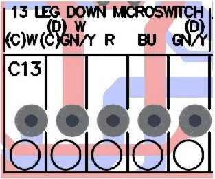
Figure 1
Figure 1 shows the wiring of the Leg Down Microswitch onto the PCB. Depending on the junction box C (Left) or D (Right), the wiring will alter.
Position |
Differences |
C |
Left hand module junction box. (On a Left Hand Lift Sidelifter this will be the front crane, on a Right Hand Lift Sidelifter this will be the rear crane). |
D |
Right hand module junction box. (On a Left Hand Lift Sidelifter this will be the rear crane, on a Right Hand Lift Sidelifter this will be the front crane). |
Code |
W |
GN/Y |
R |
BU |
Colour |
White Wire |
Green/Yellow Wire |
Red Wire |
Blue Wire |
|
For both cranes the Red and Blue wires always go to the same connector blocks, but the White and Green/Yellow wires change position, as illustrated in Figure 1 |
If the wiring is found to be correct then also check the wiring at the Microswitch which should be as follows.
Code |
W |
R |
BU |
GN/Y |
Value |
14 |
22 |
21 |
13 |
