13 Jan 2005 PDF File |
Version 1 |
Electrics |
|
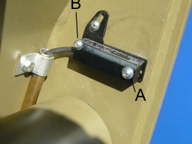
Figure 1 Angle Switch
Angle Switch Spare Part Number = EL-34354
Refer to circuit diagram SB7474-85.DWG
An angle switch is fitted to each top arm adjacent to Top Arm Lifting Cylinder Ram Eye. The purpose of the angle switches is to prevent the 'cutting out' of the Top Arm Up and Bottom Arm Down functions if the stabiliser foot lifts off the ground during a lift, unless the top arm angle is over 71° from horizontal.
The angle switches switch-off when either top arm angle exceeds 71°, however if both stabilisers are in contact with the ground full arm function is retained. If either stabiliser lifts off the ground then power is lost to the safety bypass relay (R13/B) and arm functions will be limited to Top Arm Down and Bottom Arm Up. In order for the Relay (R12/B) to be reset (thereby restoring full arm functions) the load will have to be manoeuvred so as to restore pressure to both Stabiliser feet.
Upon initial start-up both Stabiliser feet will have to be in contact with the ground before Top Arm Functions are available.
Switch-on point; in horizontal position (±1°) when the cable end is moved upwards
Switch-off point; the switching hysteresis is exceeded by moving the cable end downwards
Switching hysteresis; 2.5…5.5°
Repeatability; <0.2°
Black (BK); Power Supply 10.30V DC
Brown (BN); Earth
Blue (BU); Switched Signal
The angle switches are wired in series, the rear angle switch Signal (BU) powers the front angle switch
In Service adjustment of the angle sensor is performed as follows;
USING EXTREME CAUTION, test the functionality of the system by first positioning the container squarely above the twistlocks. Carefully lift one stabiliser leg so that a gap appears between the stabiliser extension and stabiliser housing, but not enough to lift the foot from the ground. The stabiliser warning beeper should sound. With one end of the container only carefully manoeuvre the container above the offside bash-plate and observe the cut-out position. The same procedure should be followed for putting the container onto the twistlocks, but no functional cut-out should be observed.