![]()
While in teach mode only 1 function can be activated at one time i.e. do not move the joysticks in a diagonal way.
4 Sep 1998 PDF File |
Version 1 |
Electrics |
|
Remove chains from arms before carrying out this procedure.
The radio receiver output voltage must be set to obtain the best performance from the Sidelifter. If the setting is incorrect it can result in reduced speed or low speed being inoperative due to the EHF controllers cutting out.
Remove the engine timer (alternatively the electrical connection (hershman plug) from the engine throttle air cylinder) so that the engine will only operate at idle speed.
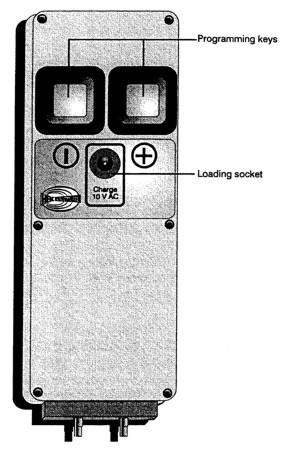
Turn off the radio remote using the key switch on the radio, depress both the "+" and "-" on the tele-teach-in battery and while they are depressed turn on the radio control via the radio key. The green lamp should now be flashing quickly. The radio control is now in teach mode. In standard non -teach mode the green lamp flashes slowly.
Start the engine and select low speed. Push the joystick towards the desired function (do not move the joystick more than 50% of its travel) until you can hear the engine throttle relay activate. Without moving the joystick from its position adjust the speed of the selected function using the "+" or "-" buttons (on the Tele-teach-in battery) until the selected cylinder stops moving. Carry out the same procedure for all of the functions. Please note that this has to be repeated again in high speed mode as well as low speed mode.
Remove the earth wire from the hour meter and connect the voltmeter -ve terminal to it. Measure the voltage at the hour meter with the engine running. This should be approximately 13.5Volts on a 12V system. Record the voltage.
To calculate the Max and Min voltages to set the radio apply the following formula.
Max voltage is set at Ẅ Input V + (3.5V for 12V system) or (6.5V for 24V system).
Min voltage is set at Ẅ Input V - (3.5V for 12V system) or (6.5V for 24V system).
e.g. Input voltage is 14V max and minimum voltage =(Ẅ 14) +3.5 & (Ẅ14V) - 3.5V
= 10.5V & 3.5V
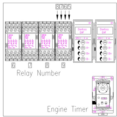
Select the mode switch to high speed and with the engine still running set each of the functions output voltage as read on ports 5,6,7 and 8 of relay 9 to the minimum and maximum voltages as calculated in step 4 above. Now set the mode switch low speed and carry out the same procedure as above.
This procedure must be repeated in all functions i.e. arms high speed, arms low speed, stabilisers high speed, stabiliser low speed, module high speed, modules low speed and for each joystick movement.
Turn off the radio control via the key and turn on again (the radio should now be back in standard mode and the green light should be flashing slowly). Start the engine. Check all the voltages at terminals 5,6,7 and 8 on relay 9 are set as described above.
|
While in teach mode only 1 function can be activated at one time i.e. do not move the joysticks in a diagonal way. |